Get in touch with QJKH Company


Updated June 2026 · Reviewed by the CCH Sensing technical team.
Collaborative robot safety is the set of design limits, collaborative operating modes, and risk controls that let a robot share a workspace with people without injuring them. It’s also one of the most misunderstood ideas in factory automation. Marketing says a cobot is “inherently safe,” so you can take it out of the box, stand next to it, and skip the fences. In reality, safety isn’t a property the robot carries around with it, it’s a property of the application: the arm, the tool on the end of it, the part it’s moving, the speed it run, and the people who share its space. Get that distinction wrong and a “safe” cobot will still send someone to the emergency room.
This guide is written by a safety-sensor manufacturer, so it is deliberately blunt about where power-and-force limiting stops and where an external light curtain, area scanner, or safety relay has to take over. We will cover the four collaborative operation modes from ISO/TS 15066, the body-region force limits that decide whether contact is acceptable, the standards stack (including the major 2025 revision of ISO 10218), how to run a risk assessment, and the five dangerous assumptions that get people hurt.
Quick Specs: Collaborative Robot Safety at a Glance
| Governing standards | ISO 10218-1 & -2:2025 (robot + cell), ISO/TS 15066:2016 (collaborative guidance), ANSI/RIA R15.06 (US) |
| Collaborative operation modes | 4 — safety-rated monitored stop, hand guiding, speed & separation monitoring, power & force limiting |
| Force/pressure limits | ISO/TS 15066 Annex A — 29 body locations; e.g. face 65 N, skull 130 N transient |
| Typical PFL speed | 250–1,000 mm/s TCP (drops as payload rises) |
| Safety device rating | PL d / SIL 2 minimum; Type 4 light curtains PL e (ISO 13849-1 / IEC 62061) |
| Mandatory step | A documented, task-based risk assessment (ISO 12100) — every application |
What Collaborative Robot Safety Really Means
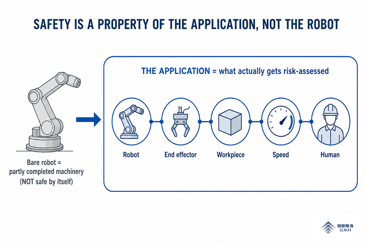
A collaborative robot, cobot for short, is a robot designed to work alongside humans without a traditional safety fence. But “designed to” isn’t the same as “is.” Here’s the principle that everything else in this guide hangs on, what we call The Application-Safety Principle: a cobot is never safe or unsafe on its own; the application is what gets risk-assessed and signed off. That same arm is safe carrying a foam probe and dangerous carrying a deburring spindle.
That matters because the robot is only one piece. Under the standards, the bare robot is “partly completed machinery”; the thing that has to be made safe is the complete cell, robot, end effector, workpiece, layout, and the people. The U.S. Occupational Safety and Health Administration is explicit that there’s no robot-specific OSHA standardrobots are regulated under general machine-guarding rules (29 CFR 1910.212) and the General Duty Clause, and “a combination of controls and safeguarding should be used.”
What makes a cobot safe?
Four things, in order: (1) the robot’s built-in safety functions, power, force, torque and speed monitoring that trigger a protective stop; (2) the collaborative operation mode you choose for the task; (3) any external safeguarding the risk assessment calls for; and (4) the risk assessment itself, which ties the first three to your tool, payload and layout.
Skip the fourth and the first three are just features on a spec sheet. Those built-in safety functions, the safety features and protective features of the robot system, the extra safety measure an integrator adds, and the safety mechanisms that fire on a collision all combine so the machine can run around people, yet none of them removes the duty to assess how human workers actually come into contact with the robot. Field experience backs this up: lighter cobots stop on light contact, but “larger ones with more inertia” hit harder, so mass and payload change the answer.
The Four Types of Collaborative Operation (ISO/TS 15066)
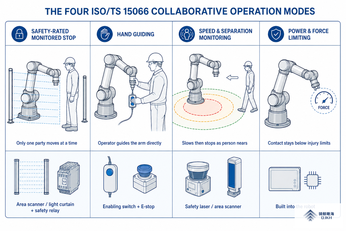
ISO/TS 15066the technical specification that supplements ISO 10218, defines four collaborative operation modes. An application can combine them, and each one implies a different stop trigger and a different safety device. This is the table the top search results describe in prose but never lay out:
| Mode | How it protects the human | Typical safety device |
|---|---|---|
| Safety-rated monitored stop | Robot holds still whenever a person is in the workspace; only one party moves at a time | Area scanner or light curtain to detect entry; safety relay for the monitored stop |
| Hand guiding | Operator moves the arm directly through a hand-operated device with an enabling switch | Enabling (three-position) switch + E-stop on the guiding device |
| Speed & separation monitoring (SSM) | Robot slows as the person approaches and stops if separation drops below a calculated distance | Safety laser/area scanner feeding a controller that modulates speed |
| Power & force limiting (PFL) | Robot limits contact force/pressure below injury thresholds, so contact is tolerable | Built into the robot (torque/force sensing); no external device for blunt contact |
Universal Robots, which helped write the standard, notes that in practice only SSM and PFL deliver genuinely fence-free collaborative applications; the monitored stop is really a faster-restarting guarded cell, and hand guiding, driving the arm through hand-guided controls, is a teaching aid. Across collaborative robot applications, human-robot contact is the variable that decides the mode, so pick the mode for the task, not the other way round.
Power & Force Limiting: The Body-Region Force Ceiling
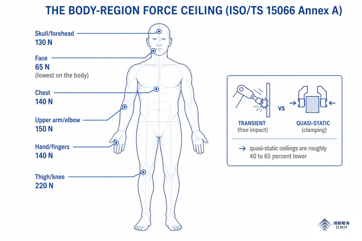
Power and force limiting is the mode people mean when they say “cobot.” It works by guaranteeing that any contact stays below the point where a human feels pain or injury. Those thresholds are not a marketing number, they come from ISO/TS 15066 Annex A, which sets maximum permissible force and pressure for 29 specific body locations (grouped into 12 body areas), based on pain-onset research. We call this reference The Body-Region Force Ceilingand almost no competing guide prints it:
| Body region | Max transient force (N) | Max transient pressure (N/cm²) |
|---|---|---|
| Skull / forehead | 130 | 110 |
| Face | 65 | 110 |
| Chest | 140 | 110 |
| Upper arm / elbow | 150 | 130 |
| Hand / fingers | 140 | 200 |
| Thigh / knee | 220 | 160 |
Two numbers in that table do the most work. First, the face at 65 N is the lowest force ceiling on the body, which is why a cobot working near head height needs extra scrutiny. Second, the standard splits every limit into transient (a free impact, where the body can move away) and quasi-static (clamping or trapping, where it can’t). Quasi-static ceilings run roughly 40–65% of the transient values, because sustained compression damages tissue at lower force.
📐 Engineering Note: a worked force check
Suppose your PFL cobot can trap a hand against a fixture (quasi-static, hand region). Take the transient hand limit of 140 N and apply the ~50% quasi-static factor → a clamping ceiling near 70 N. If a force-test gauge during validation reads 95 N at that pinch point, the application failsyou must lower payload/speed, redesign the fixture to remove the trap, or add a presence device so the arm cannot reach that pose while a hand is there. This is why ISO 10218-2 requires measured force during commissioning, not just the manufacturer’s default settings.
Practically, PFL cobots run between 250 and 1,000 mm/s, and the permissible speed falls as the effective mass (robot + payload + gripper) rises. Engineers patenting this field, for example US 11,453,122 B2, a torque-sensor-per-axis collaborative system, are all chasing the same thing: detect the contact fast enough to stop under the limit. In practice the amount of force and the torque applied at every joint must stay under the allowable ceiling, and the end-of-arm tooling, an electric or pneumatic gripper, counts toward it, because a sharp tool raises the risk of injury even when the arm itself is compliant.
Speed & Separation Monitoring: Letting a Cobot Run Faster
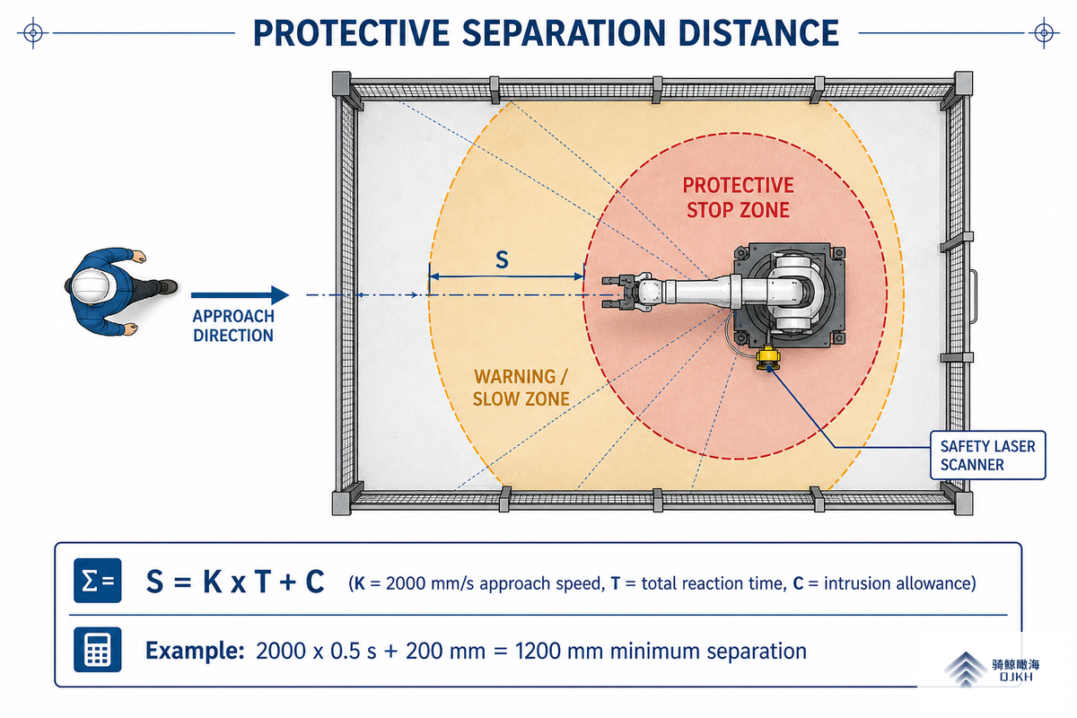
The trouble with PFL is that staying under the force limits forces the robot to crawl, Universal Robots admits the speed “will likely be too low to be useful for high-risk applications.” Speed and separation monitoring fixes this by keeping a measured gap between human and robot. When the operator is far away the robot runs at production speed; as they approach it decelerates; if the gap drop below the minimum protective separation distance, it stops.
That distance is calculated, not guessed. ISO 13855 gives the form S = K·T + C, where K is the human approach speed (the standard value is 2,000 mm/s), T is the total system reaction time (sensor response + robot stopping), and C is an intrusion/uncertainty allowance.
📐 Engineering Note: sizing the separation distance
Say a safety laser scanner plus controller plus robot give a total reaction time T = 0.5 s, and you allow C = 200 mm for hand intrusion. Then S = 2,000 mm/s × 0.5 s + 200 mm = 1,200 mm. The scanner’s “stop” zone must start at least 1.2 m from the nearest reachable hazard. Halve the reaction time (faster scanner, shorter stop) and the footprint shrinks to 700 mm, which is exactly why response time, not list price, is the spec that matter when you choose a safety laser scanner for an SSM cell.
SSM is where an external sensing layer earns its keep. The NIST testbed work and the peer-reviewed SSM literature both stress that the sensing must itself be safety-rated and validated, not a standard automation scanner repurposed for safety. Our safety laser scanner guide walks through zone configuration in detail.
The Standards Stack: ISO 10218, ISO/TS 15066 and ANSI/RIA R15.06
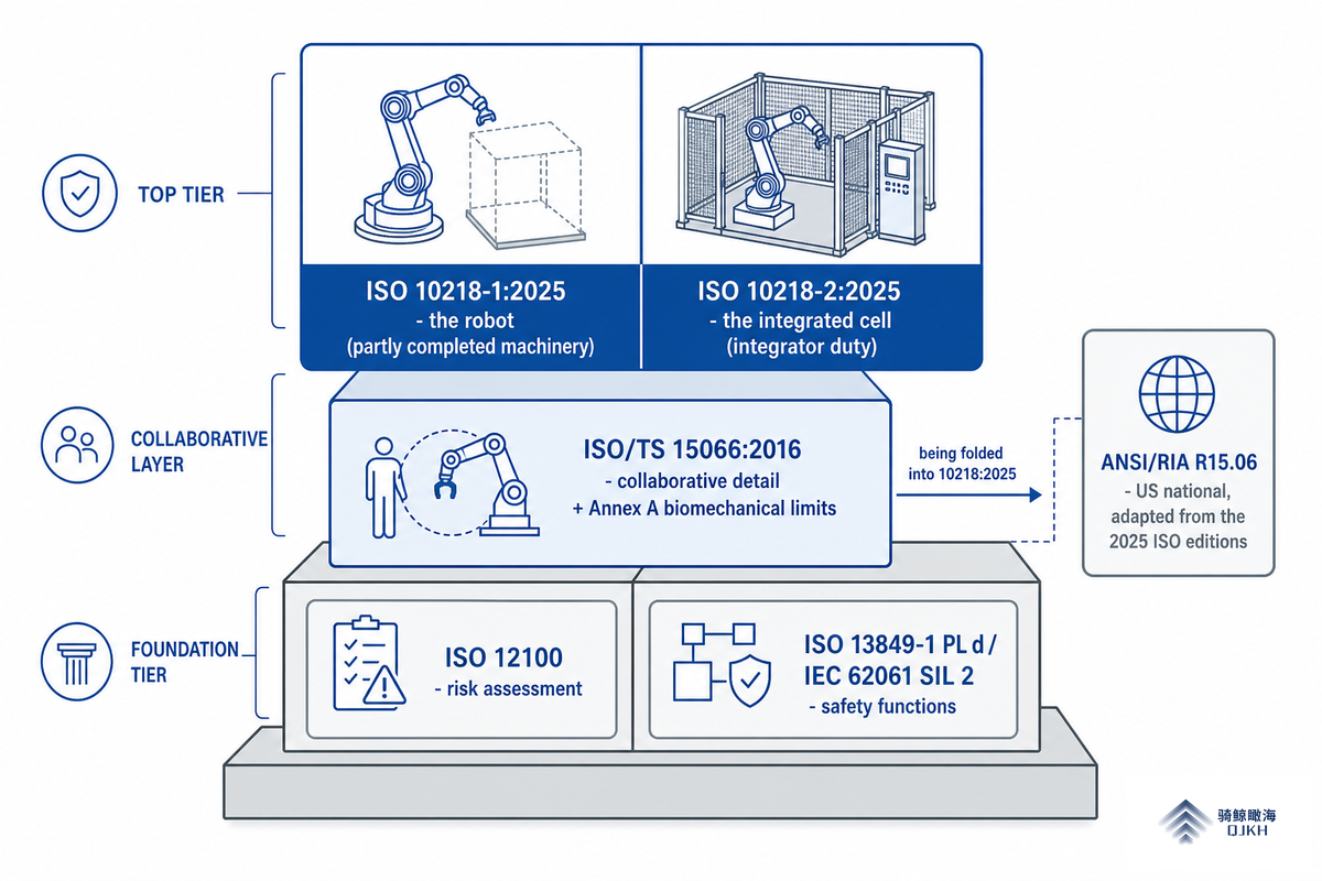
Three documents govern cobot safety, and they’re layered, not interchangeable:
| Standard | Covers | Region / status |
|---|---|---|
| ISO 10218-1:2025 | The robot as partly completed machinery (built-in safety functions) | International · 3rd edition, Jan 2025 |
| ISO 10218-2:2025 | The integrated robot cell/application (your responsibility as integrator) | International · 3rd edition, Jan 2025 |
| ISO/TS 15066:2016 | Collaborative-operation detail + biomechanical limits (Annex A) | International · being folded into 10218:2025 |
| ANSI/RIA R15.06 | US national robot safety, adapted from ISO 10218 | United States · revised from the 2025 ISO editions |
The hierarchy underneath them matters too: risk assessment follows ISO 12100, and safety functions must hit a performance level (PL d per ISO 13849-1) or safety integrity level (SIL 2 per IEC 62061) appropriate to the risk. Roberta Nelson Shea, Universal Robots’ Global Technical Compliance Officer, long-time convenor of the ISO robot-safety committee, and the leading authority on these documents, has spent decades stressing that the standard is a floor, not a ceiling.
When a “Fenceless” Cobot Still Needs Guarding
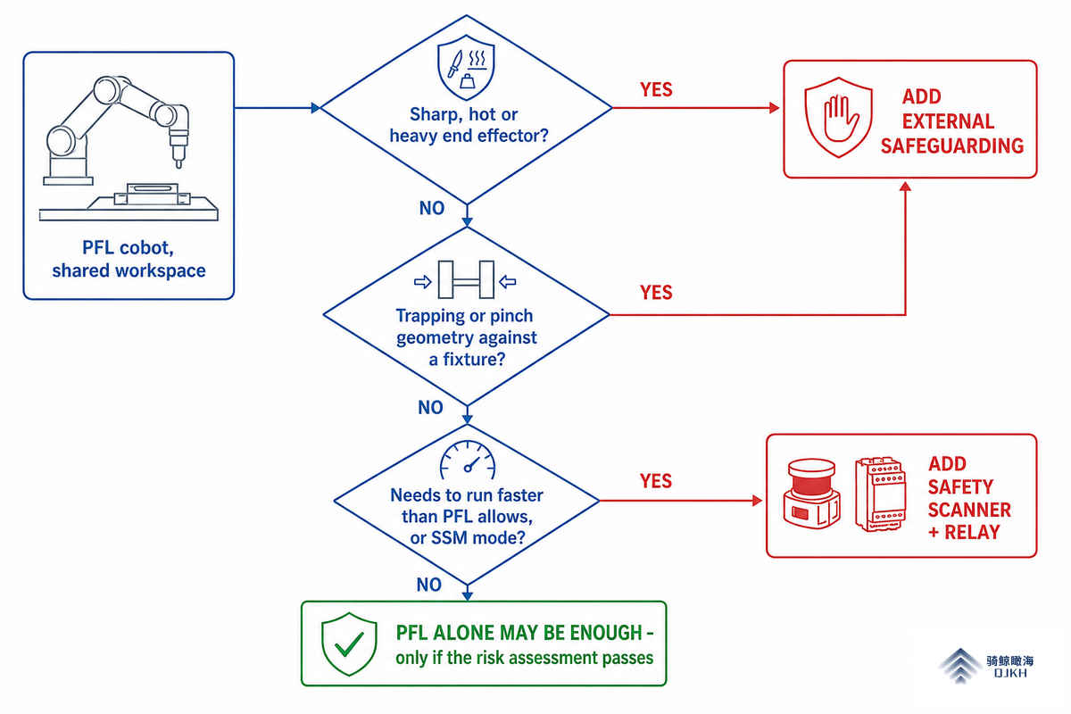
Here’s the part the cobot brochures skip. A power-and-force-limited robot manages blunt contact, it does nothing about a sharp, hot, or heavy end effector. Robotiq’s own palletizing example makes the point: moving multi-kilogram boxes at head height is “intrinsically unsafe,” so above a crawl that cell require a safety device regardless of PFL.
✔ When PFL alone is usually enough
- Blunt, lightweight gripper and payload (< ~3 kg)
- Low speed, no trapping/pinch geometry near the body
- Light assembly, inspection, lab handling
⚠ When you must add external safeguarding
- Sharp/hot tool, welding tip, blade, or unguarded spindle
- Heavy payload or fast cycle (palletizing, machine tending at speed)
- SSM mode (needs a scanner) or a clamping/trap hazard
Are cobots safe to work without a fence?
Sometimes, and only when the risk assessment proves it for that exact tool, payload, speed, and layout. Trigger questions: can the end effector cut, burn, or crush? Can a body part be trapped against a fixture? Does the cycle need to run faster than PFL allows?
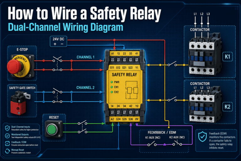
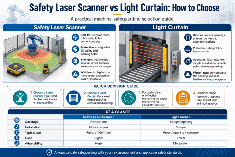
If any answer is yes, add a presence-sensing layer, a safety light curtain at a load station, an area scanner for floor zones, and a safety relay to execute the monitored stop. Each device must carry a rating matched to the risk (PL d/SIL 2, or Type 4 PL e for finger protection). For a side-by-side of the presence devices, see our scanner vs. light curtain comparison and the broader machine-guarding light curtain overview.
The 6-Step Cobot Risk Assessment Walk
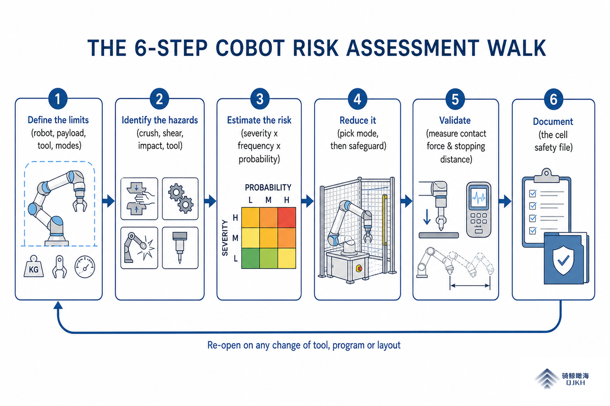
Every standard points back to the same task-based process from ISO 12100. Here is The 6-Step Cobot Risk Assessment Walk we use, condensed:
From application to signed-off cell
- Define the limitsrobot model, payload, end effector, workpiece, cycle time, and every mode including setup, jam recovery, maintenance and foreseeable misuse.
- Identify the hazardscrushing, shearing, impact, the tool, the workpiece, plus electrical/thermal. Walk each operating phase.
- Estimate the riskseverity × frequency × probability × avoidability, via a risk graph (ISO 12100 Annex A).
- Reduce itpick the collaborative mode, then add safeguarding only where the mode can’t carry the risk (the hierarchy: design out → safeguard → inform).
- Validatemeasure actual contact force (PFL) and actual stopping distance (SSM); compare to the limits and the calculated S.
- Documentthe assessment, the safety-circuit design, and the test records become the cell’s safety file. Re-open it on any change of tool, program, or layout.
Done well, the process is really risk reduction in stages: you reduce the risk by choosing the mode first, then layer safety controls and a safety system sized to the specific safety requirements and safety needs of that robotic system. Operators still need a robot safety training program covering the cell’s safety protocols before the line run. One discipline most teams miss: the risk assessment is a living document, so a new gripper or a new part program changes the risk profile and forces a review, a point industry trainers and groups like SACA keep repeating.
5 Fenceless-Cobot Assumptions That Get People Hurt
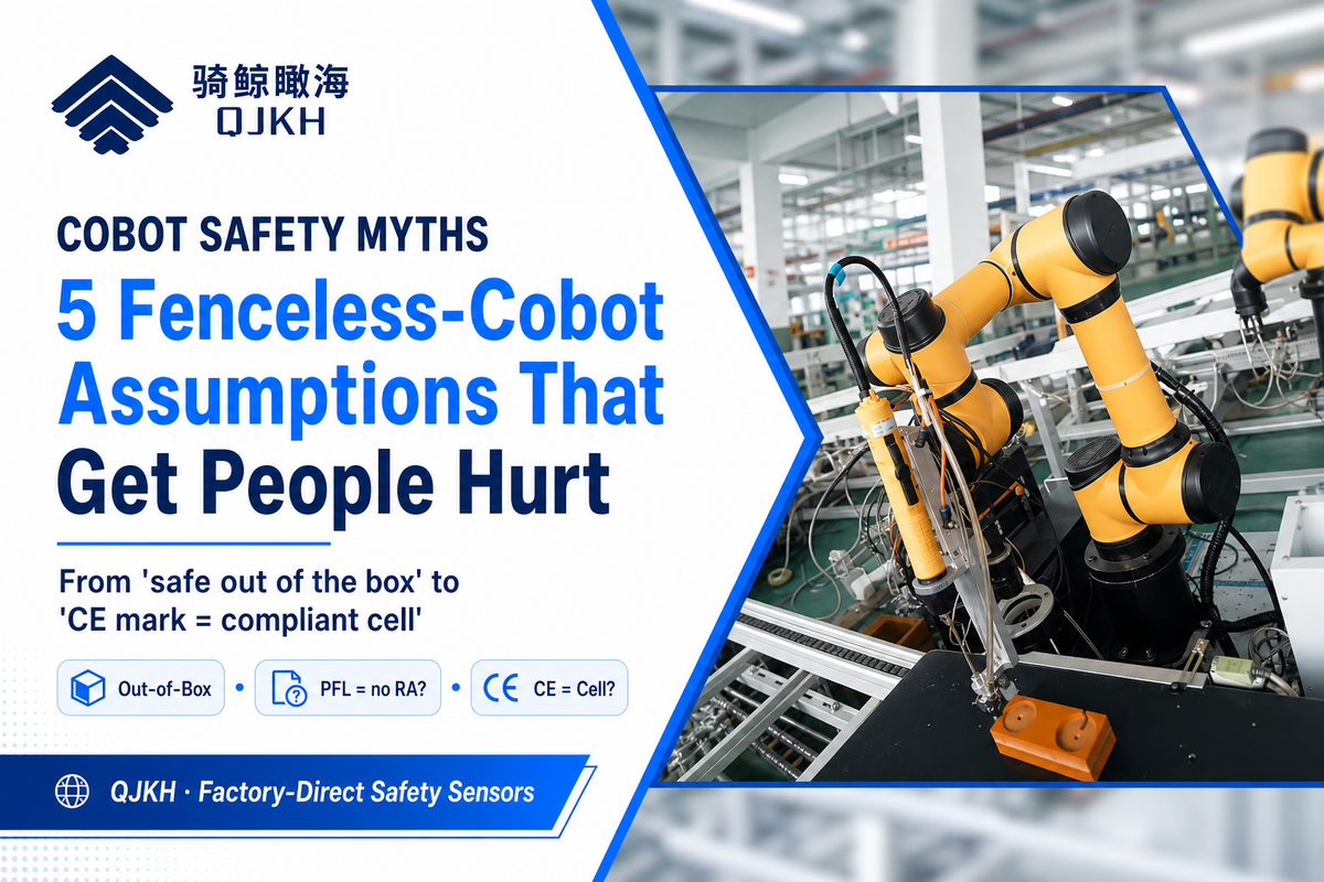
From field experience and the standards, these are the assumptions worth auditing before anyone stands next to the arm:
- ⚠️“A cobot is safe out of the box.” The robot is partly completed machinery; only the assessed cell is safe.
- ⚠️“PFL means no risk assessment.” Force limiting addresses blunt impact only, it says nothing about your tool, and the assessment is still mandatory.
- ⚠️“Slow always means safe.” A slow arm with a blade, a hot tip, or a clamping fixture still injures.
- ⚠️“Any gripper and payload are fine.” Effective mass sets the speed ceiling; a sharp or heavy payload can void PFL safety entirely.
- ⚠️“A CE-marked robot means a compliant cell.” The robot’s mark covers ISO 10218-1; the integrated cell needs its own conformity under 10218-2.
Why isn’t cobot safety as simple as it first appears?
Because the marketing answers a different question than the standard does. “Is the robot safe?” gets a confident yes; “is this robot application safe?” gets “it depends on the tool, the speed, and the people.” Applied Manufacturing Technologies puts the most common error plainly: the misconception that operators can share the same space as a PFL robot with no guarding “isn’t always” correct.
A peer-reviewed socio-technical review reaches the same conclusion, machines don’t always behave as assumed, so the inherent-safety belief has to be tested, not trusted.
Cobot Safety by Application: The Four-Mode Fit Test
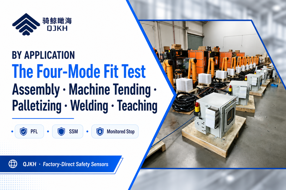
Different jobs land on different modes and different devices. Use The Four-Mode Fit Testmatch the application to its likely mode and the safeguarding it usually needs:
| Application | Likely mode | Usual safeguarding |
|---|---|---|
| Light assembly / inspection | PFL | None beyond the robot, if the assessment passes |
| Machine tending at speed | SSM or monitored stop | Area scanner + safety relay; light curtain at the load door |
| Palletizing | SSM | Laser scanner zoning (boxes at head height = high risk) |
| Welding / deburring | Monitored stop | Full perimeter guarding (hot/sharp tool overrides PFL) |
| Lead-through teaching | Hand guiding | Enabling switch + E-stop on the guide device |
Whatever the application, the safe-stop function in the background is usually a safety relay module tying the sensors to the robot’s safe inputs. For a full traditional robot-cell layout, the caged cousin of the collaborative cell, see our safety for robot cells solution.
“The question we ask integrators is never ‘is the cobot safe?’ — it is ‘what does the end effector do, and how fast?’ On a finger-protection load station we still specify a Type 4 PL e light curtain even on a force-limited arm, because PFL does nothing about a 200 N/cm² pinch from a sharp gripper.”
CCH Sensing Application Engineering team
Industry Outlook: What ISO 10218:2025 Changes for Your Next Cobot
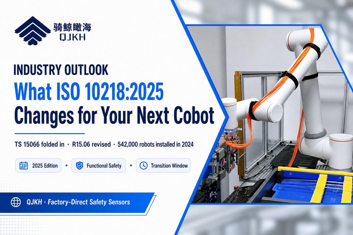
The most important recent change is regulatory, not technological. In January 2025 the third editions of ISO 10218-1 and ISO 10218-2 were jointly published, and they make functional-safety requirements explicit rather than implied, and fold the collaborative content that lived in ISO/TS 15066 into the 10218 series itself. Shortly after, ANSI and A3 published a revised R15.06 adapted directly from the 2025 ISO editions.
For a buyer or integrator, the action item is concrete: stop treating ISO/TS 15066 as a standalone spec, and confirm which edition your robot OEM and your integrator are certifying to on your next install. A cell designed and documented against the 2011 standard is not automatically wrong, but during a transition window auditors and customers will increasingly expect the 2025 baseline. For context on scale, the reason the standards bodies moved, the IFR’s World Robotics 2025 report counted 542,000 industrial robots installed in 2024, the fourth straight year above 500,000; that volume of human-adjacent automation is what drove the rewrite (market figures here are background only).
On the horizon, skin-like tactile sensors and AI-vision human tracking promise faster, finer detection and better safety performance, but neither is yet certified for advanced safety use, so across real use cases the compliant fence-free cell still rests on the four modes, the force ceilings, and a documented risk assessment. Robotic safety of industrial robots and robot systems, collaborative or not, is still earned application by application.
Frequently Asked Questions
Q: Are collaborative robots really safe?
View Answer
They can be, but safety is a property of the application, not the robot. A cobot has built-in force, speed and torque limiting, yet the same arm is safe with a foam tool and dangerous with a blade. A documented risk assessment that covers your end effector, payload, speed and layout is what makes a specific cobot installation safe — and OSHA still regulates it under general machine-guarding rules.
Q: Do cobots need a risk assessment?
View Answer
Yes — always, with no exception, under ISO 10218-2 and ISO 12100. Power and force limiting does not remove the requirement; it only addresses blunt contact. That assessment defines limits, identifies hazards, estimates and reduces risk, then validates by measuring actual contact force and stopping distance. It must be re-reviewed whenever the tool, program, payload or layout changes.
Q: What’s the difference between a cobot and an industrial robot?
View Answer
A traditional industrial robot prioritizes performance and assumes a guarded, human-free workspace — it will hit you at full force without detecting you. A collaborative robot is designed so contact stays below injury thresholds (power and force limiting) or so it slows and stops as you approach (speed and separation monitoring), allowing shared workspace once a risk assessment confirms the application is safe.
Q: Can a cobot work without any guarding?
View Answer
Only in power-and-force-limiting mode, at low speed, with a blunt, lightweight tool, and only if the risk assessment proves it. Add a sharp tool, more speed, or a trap hazard and external safeguarding becomes mandatory.
Q: Which standard covers collaborative robots, ISO 10218 or ISO/TS 15066?
View Answer
Both, layered. ISO 10218-1 and -2 are the core safety standards for the robot and the integrated cell; ISO/TS 15066 is a technical specification that adds collaborative detail, including the Annex A biomechanical limits. Every collaborative installation needs full ISO 10218 compliance, with TS 15066 used for the collaborative specifics — and in the 2025 edition that collaborative content is being consolidated into ISO 10218 itself.
Q: Does ISO 10218:2025 replace ISO/TS 15066?
View Answer
Largely, yes — going forward. The third editions of ISO 10218-1 and ISO 10218-2, published in January 2025, absorb the collaborative-operation requirements that previously lived in ISO/TS 15066, and make functional-safety requirements explicit rather than implied. ISO/TS 15066:2016 remains a useful reference for the Annex A biomechanical force and pressure limits, which engineers still cite directly, but the normative home for collaborative requirements is now the 10218 series. ANSI/RIA R15.06 has already been revised to match, so US integrators should design new cells to the 2025 baseline and confirm which edition their OEM certifies to.
Why We Write This
CCH Sensing builds the safety laser scanners, Type 4 light curtains and PL e / SIL 3 safety relay modules that integrators bolt onto collaborative robot cells when power-and-force limiting isn’t enough. This guide reflects the questions our application engineers field every week, almost always about the boundary between what the cobot handle and what an external sensing layer must cover. Reviewed by the CCH Sensing technical team.
Designing a collaborative or fenceless robot cell and not sure where PFL stops and a sensor has to start?
References & Sources
- ISO/TS 15066:2016, Robots and robotic devices: Collaborative robotsInternational Organization for Standardization
- ISO 10218-1:2025, Robotics, Safety requirements, Part 1ISO
- Robotics, OverviewU.S. Occupational Safety and Health Administration
- 29 CFR 1910.212, General requirements for all machinesOSHA
- Implementing Speed and Separation Monitoring in Collaborative Robot WorkcellsNIH/PMC
- NIST IR 7851, Testbed for Speed and Separation MonitoringNational Institute of Standards and Technology
- Updated ISO 10218, FAQAssociation for Advancing Automation (A3)
- World Robotics 2025, Industrial RobotsInternational Federation of Robotics