Get in touch with QJKH Company
A Safety Area Scanner is a Type 3 certified safety device perched at the intersection of three things a product datasheet never shows you: a risk-graph calculation, a minimum-distance formula, and a dozen small installation decisions that determine whether the device actually stops a machine to protect personnel before a human reaches the hazard. This guide walks through the standards, the mathematics, and the field-commissioning mistakes that separate a scanner shipping with a certificate from one that performs on the shop floor.
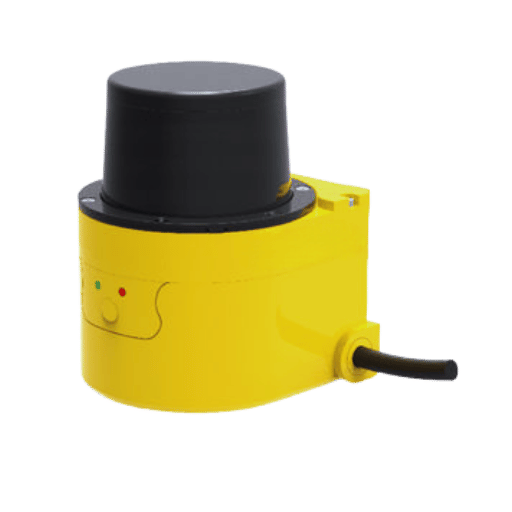
Quick Specs — Safety Area Scanner Essentials
| Detection principle | Diffuse-reflection time-of-flight laser (IEC 61496-3) |
| Typical protection range | 3 – 8 m, e×tendable warning zone to 40 m |
| Scanning angle | 270° – 275° |
| Safety rating | Type 3 / SIL 2 / PLd, Category 3 |
| Response time | 60 – 120 ms (scanner only; full system time drives safety distance) |
| Governing formula | S = (K × T) + DDS + Z (ISO 13855:2024) |
What a Safety Area Scanner Actually Does (Beyond the Datasheet)
A safety zone scanner diver sends short infrared laser pulses through a rotating mirror that searches the beam through a 270 to 275 arc in front of the device. For each pulse, the scanner measures the time delay between emission and reflection from whatever surface the beam hits – human, pallet, wall, or the floor at the perimeter of the detection range. That time-of-flight measurement translates directly into a distance measurement, and several thousand such measurements per scanner cycle construct a twodimensional polar map of the scannerner’s environment. When any measurement enters a preconfigured protection zone, the scanner de-energizes its OSSD safety outputs, and the downstream controller stops the hazardous motion. This is how the device is capable of detect objects – human or otherwise – that cross a configurable zone boundary and hand that event to the safety control system as a certified signal.
Mechanism matters because it determines what a safety zone scanner diver can and cannot do. Unlike a light curtain, which detects interruption of a beam across a single plane, a scanner provides an area-based safety solution. The warning zone and protection zone can be arbitrary shapes plotted on configuration software, switched between banks without hardware modifications, and traversed between zones in under one scanner cycle. This is why a scanner substitutes hard guarding and safety mats wherever layout changes are forecasted – no wire fatigue, no mat replacement after dropped tools, no fence rewiring when the cell relocates. Across today’s automation, that adaptability is what allows a single safety zone scanner to achieve zone flexibility that older contact-based guarding cannot.
A laser beam emitted in a fan shape also means detection resolution worsens with distance. At 3 m from the scanner, a 30 mm object is detectable; at 8 m, the minimum detectable object is generally 70 mm. This geometric detail informs both the mounting-height selection and the minimum-distance calculation presented subsequently in this guide.
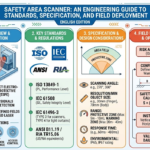
The Safety Standards Stack — IEC 61496, IEC 61508, and ISO 13849
Three standards specify what a certified safety area scanner must deliver. They stack one upon the other — each addresses one question, and all must be answered for the scanner to be certified.
| Standard | Role in the Stack | What It Requires of the Device |
|---|---|---|
| IEC 61496-3 | Product-level: the scanner as a device | Classifies opto-electronic protective equipment (ESPE) based on reflection; Type 3 = self-monitors all specified faults and tolerates a single component failure without losing the safety function. |
| IEC 61508 | System-level: functional safety | Assigns a Safety Integrity Level (SIL) based on probability of dangerous failure per hour (PFH). SIL 2 devices sit between 10⁻⁷ and 10⁻⁶ PFH — one dangerous failure every 100,000 to 10 million operating hours. |
| ISO 13849-1 | Machine-level: safety-related control parts | Assigns a Performance Level (PL) from a to e based on PFH, MTTFd, and diagnostic coverage. PLd sits in the same 10⁻⁷ to 10⁻⁶ PFH band as SIL 2. Category 3 describes architecture — a single fault must not cause loss of the safety function. |
What is the ISO 13849 PLd, Category 3 standard?
ISO 13849-1 refers to “PL” as a Performance Level – a classificisation of the probability of safe related parts of a control system to perform their safety function under foreseeable conditions. “PLd” refers to a scanner architecture that falls within the 10 to 10 PFH range, that is about 0.00001% to 0.0001% chance of dangerous failure per hour of operation. Category 3, added in addition to the PL value, describes the structural requirement that the total safety functionality must survive a single fault, at any point in the safety chain. These two attributes are grouped together because a PL without Category tells you how reliable, Category without PL tells you how fault tolerant – you will need both.
In practice a Type 3 scanner will also have to meet environmental conditions – detectable minimum target reflectance, minimum ambient light resistance, dirt and residue protection, operating temperature and humidity range, vibration and shock, electromagnetical compatibility. Type 4 exists as a more demanding option and is used mainly for safety light curtains based on image sensing. For maximum detection range from reflection, Type 3 is the limit set by the physical principles and that is the label that you will find on any certified area scanner.
Risk Assessment to Performance Level — The 4-Step Specification Workflow
One common mistake in scanner specification is to begin with selection model. The correct starting point is the hazard itself. ISO 12100 defines the hazard rating method. ISO 13849-1 Annex A then turns that risk assessment into a numerical Required Performance Level (PLr). Only once PLr has been arrived at does the scanner become a specification choice.
Our 4-Step Specification Workflow formalizes this ordering, and it is the keystone of any safeguard device selection that will pass an auditor.
- ✔
Step 1 — Hazard identification (ISO 12100). Walk the equipment. Catalog every point where motion, energy, or material movement can injure an operator. This is not a scanner decision yet. - ✔
Step 2 — Risk graph (ISO 13849-1 Annex A). For each hazard, pick three parameters: S (severity — S1 reversible vs S2 normally irreversible injury), F (frequency — F1 below every 15 minutes and below 1/20 of operating time, F2 above), and P (avoidance — P1 possible under specific conditions, P2 scarcely possible). Trace the graph to the required PL (PLr), somewhere from a to e. - ✔
Step 3 — Scanner specification. Select a device whose achieved PL (from the manufacturer’s certificate) meets or exceeds PLr. Most industrial machinery with a zone-control safety function lands on PLd, Category 3 — and that is where Type 3 scanners sit. - ✔
Step 4 — Safety distance and zone design. Calculate the ISO 13855 minimum distance and design the protection zone geometry around it. This is where Step 3 feeds back: a slow-responding scanner demands a larger zone, which may rule out a compact cell.
Case Study: a fenceless co-operative robot cell where an operator can touch a moving arm. Severity is S2 as the arm can deliver a crush injury. Frequency is F2 because operator interaction occurs every few minutes. Avoidance is P2 because the arm moves faster than a step-back reflex. The graph arrives at PLr=e. A Type 3 scanner rated PLd will not satisfy this alone – a PLe solution normally needs redundant safety channels or a more highly rated device. This is the kind of outcome work on hazard graph can produce, and it is the only sure method of knowing if one scanner will do the trick.
Calculating Safety Distance — The ISO 13855 Minimum Distance Formula
The most important calculation in safeguard design is the minimum separation distance between protection zone edge and hazard. Too short and the operator reaches the hazard before the machine is stopped. Too long and the operating workspace is needlessly constrained. The EN ISO 13855:2024 edition formalizes this calculation.
📐 Engineering Note — Minimum Distance Formula (ISO 13855:2024)
S = (K × T) + DDS + Z
- S – minimum separation distance, mm (never below 100 mm)
- K – approach speed: 2000 mm/sec for upper-limb access 1600mm/sec for walking (that latter minimum only if S greater than 500 mm)
- T – overall system response time in seconds being sum of scanner response, safe controller operation, and machine stop transients
- DDS – device-dependent addition for the detection capacity of the scanner (replaces the “C” term in the pre-2024 formula)
- Z – application factor for measurement uncertainty, reflection allowance, and braking delta
The distance-before-device rule: calculate S before choosing the scanner. The formula reveals which factor is actually negotiable. T is the big switch—that is, a PLC with a 20 ms safety cycle, plus a scanner at 80 ms response, plus a drive that takes 300 ms to reach zero torque, gives T = 0.4 s. At K = 1600 mm/s, that T alone adds 640 mm of distances needed. Halve T to 200 ms by means of a faster PLC reduces that contribution to 320 mm. Steering the scanner model rarely pushes the needle as much as changing stop-time elsewhere in the chain.
For the DDS (detection-capability supplement) term, the pre-2024 convention used C = 8 (d 14 mm) for object resolutions below 40 mm, where d is the scanner’s minimal detectable object. A scanner with 30 mm resolution would give C = 128 mm. For resolutions between 40 and 70 mm – typical at greater scanner distances – the convention defaults C to 850 mm. These values persist into the 2024 DDS system because they describe the same physical circumstance: a rougher scanner needs a longer run-up distance prior to detection accomplishment.
Full stop-time T is rarely what a PLC report states. Field-testing often reveals T to be 10 to 20 % higher than the controller states because mechanical drives decelerate in a non-linear fashion and the drive report stops at the command signal, not at physical rest. A stopwatch-calibrated bench testing session with a calibrated test rod in hand is the only real-world validation that qualifies.
Installation and Commissioning Without the Foot-Gun Mistakes
Scanner certification establishes capability; proper installation ensures operation. Several simple missteps appear time and again in facility-wide machine-safety audits and in the field reports which come from equipment manufacturers. The list below shows the common missteps which have gotten machines expensively recertified, or in the worst cases caused injuries.
- ✔Mount height versus resolution. A scanner mounted 300 mm off the floor with a 70 mm resolution represents the most common operational failure—a human can crawl underneath. Reduce the mounting height below 300 mm; reduce resolution to 50 mm. Field reports from equipment manufacturers identify this as the single most common setup error.
- ✔Multiple-sampling delay. Scanners take multiple readings — 2x, 4x, or 8x — before setting off the trigger to filter out noise. The default 2x works well in a silent, stationary setup; 4x is typical for mobile equipment, 8x is the standard for dusty, particulate environments. Increasing the sampling delay proportionally increases the off-delay, which is fed directly back into T and ultimately creates a larger safety zone.
- ✔Reflective-background allowance. A highly reflective surface within 1.5 m of the protection zone boundary adds 200 mm to the required safety distance. Chrome-plated fixtures, mirror finishes, stainless walls, and polished rollers are typical offenders.
- ✔Direct sunlight on the optical window. Infrared saturation causes false trips, not safety failures — the scanner remains safe, but availability drops. Orient the window away from sun-exposure angles that occur during shift hours.
- ✔Restart interlock per ISO 10218-2. For industrial robot cells, the safety function must not auto-restart when the zone clears; a manual reset is required. Wire this into the safety controller, not a standard PLC input.
- ✔Field-set switching via a safety channel. Zone-bank selection controlled by a non-safety PLC output downgrades the entire safety function from PLd/SIL 2 to PLc or PLa. Use safety-rated signals for bank switching, or move bank logic into the safety controller.
- ✔Bench-measured total stop time. Never trust the PLC’s reported T. Use a calibrated test rod and a stopwatch to measure from zone penetration to physical motion cessation. The measured value is the T you feed into the ISO 13855 calculation.
- ✔Blind-spot coverage for corners. A single 275° scanner mounted on a corner leaves a wedge-shaped dead zone behind the mounting bracket. Two scanners at adjacent corners, with protection zones that overlap in the corner region, are the typical solution for AGVs and large cells.
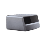
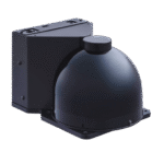
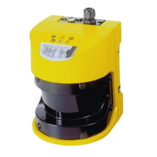
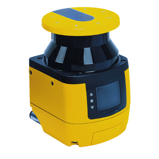
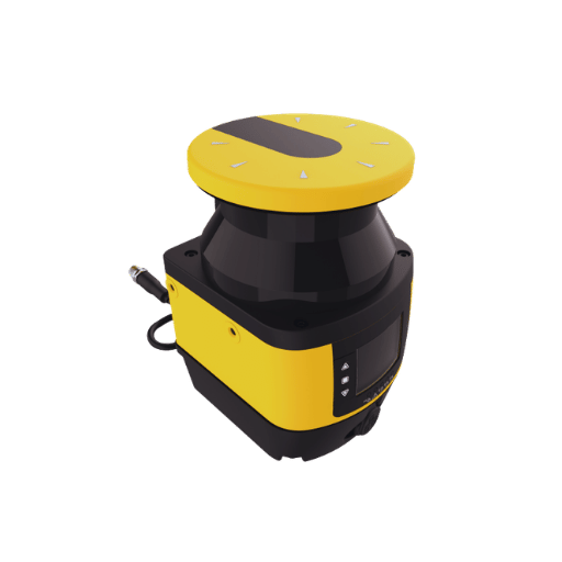
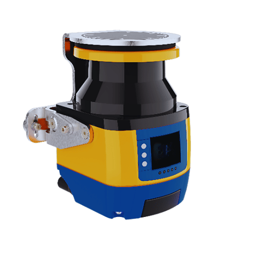
Hardware selection that delivers the previously-described PLd/SIL 2/Type 3 stack is covered by the QJKH QAS range of Type 3 certified safety scanners, covering the three typical distance ranges for stationary, AGV, and fenceless-cell approaches.
Zone Design for AGV, Robot Cell, and Muted Conveyor Applications
Zones is where the scanner power meets application needs. Software tool can draw just about any shape as a protection or warning zone, but does not recommend which zone shape is best for a particular installation. A rule of thumb is simple: protective zones should be as big as necessary but as small as practicable. Too-large zones will trigger nuisance stops, too-small zones violate the ISO 13855 calculation.
| Application | Zone Design Principle |
|---|---|
| AGV / AMR navigation | Speed-scaled zone banks: narrow travel-zone at 2 m/s corridor cruise, wider crossing-zone at intersections, precision docking-zone at charging bays. Hysteresis thresholds on the velocity signal prevent bank-flapping on gentle acceleration changes. |
| Fenceless robot cell | Two-tier zone layout: warning zone triggers a slowdown to ISO 10218-2 safe reduced speed; protection zone triggers full stop. Overlap multiple scanners at cell corners to eliminate wedge blind spots behind mounting hardware. |
| Muted conveyor pass-through | Programmable muting window matched to product silhouette. Unprogrammed intrusion (a hand or an out-of-spec package) still triggers a stop. Muting logic must use two independent muting sensors per the ANSI B11.19 and ISO 13849 architecture rules — single-sensor muting is not a certifiable safety function. |
| Forklift access aisles | Wide warning zone with narrow protection zone, because full stops at forklift speeds are operationally expensive. Warning triggers an audible alert and speed reduction; protection triggers the stop. Bank-switching by lane position is common. |
Multipoles installs increasingly use CIP Safety over EtherNet/IP, or PROFIsafe over PROFINET. Both pass configurable scanner-zone states in an existing safety network, cutting-out the additional safety I/O cabling traditional installs require. Both are sufficiently standardized that a Siemens TIA Portal safety automation program or an Allen-Bradley GuardLogix program can directly read zone state, without proprietary coding. The cost is ease of commissioning – a networked scanner is more difficult to commission than one wired directly, but the wiring savings of a multi-scanner installation generally more than offsets this.
Real-World Failure Modes — Reflective Surfaces, Ambient Light, Dust, and Alignment Drift
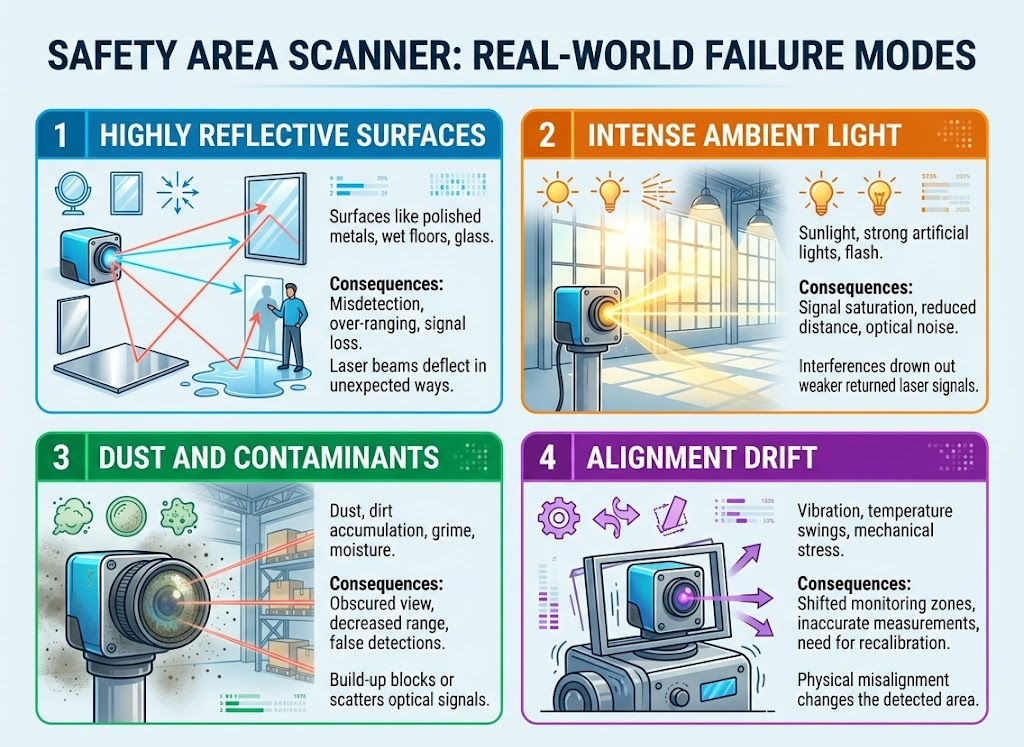
Every scanner installation eventually confronts the physical world. Our Scanner Failure-Mode Taxonomy catalogs the field problems that show up after a few weeks of operation. A Type 3 scanner will not trip when nothing moves through the protection zones – but it may still trip during no-motion, or trip too frequently to be comfortable, causing operators to disable safety altogether.
| Failure Category | Specific Symptom | Diagnostic Signal |
|---|---|---|
| Reflective | False trips near chrome fixtures, stainless rollers, mirror-polished product surfaces; distance-calculation errors near reflective walls within 1.5 m of zone boundary | Trips cluster at the same geometric location; intensity logs show saturation from off-axis reflection |
| Ambient | Direct sunlight on optical window, fluorescent lighting flicker, external infrared sources at a specific time of day | Trips show a time-of-day pattern; outdoor installations lose availability during heavy rain, snow, fog, or at dawn and dusk sun angles |
| Environmental | Dust, steam, fogging of the optical window, welding slag spatter, wood chips and dandelion seeds in outdoor yards | Availability degrades gradually over days; increasing multiple-sampling from 2x to 4x or 8x restores availability at the cost of added T |
| Drift | Mounting bracket vibration loosens over months; optical-axis angle shifts by degrees; configured zones no longer align with physical reality | Compare a fresh scan of stationary objects against the commissioning baseline; drift shows as systematic angular offset across all static reference points |
⚠️ Important — Availability is not Safety
A Type 3 scanner that trips in heavy fog is functioning as intended. It assumes unknown reflections may be a person and halts the machine. The commissioning authority must decide whether the site’s availability tolerance permits this. If a scanner trips twice per shift in a ambiention, the operators will disable it within a month.
Dedicated outdoor scanner versions with multi-echo filtering push usability into rain and snow in the hour or two surrounding the peak sunlight window. At the washdown end of the indoor spectrum, an IP65 enclosures handles short-term misting but not long-term industrial single-hose/high-flow rinse – validate the IP code against the washdown routine before including a scanner on a food or pharma product line. The remote-monitoring firmware the scanner supplies, when the scanner supplies it, allows maintenance engineers to monitor intensity and zone-state logs over a network and detect drift before it results in a downtime event.
Frequently Asked Engineering Questions
Q: What is the difference between Type 3 and Type 4 safety laser scanners?
View Answer
IEC 61496 classifications are prevailing. For what’s a safety area scanner does, IEC 61496, Type 3. For what’s a dedicated safety light curtain, IEC 61496, Type 4. For an automated guided vehicle, IEC 61496, Type 4. A “safety area scanner” in the Type 4 sense (application dependent; it’s not a universal) does not currently exist on the market because the detection-based detection needed to reach Type 4 integrity exceeds the scanner cost envelope and application justifies. For machine-guarding area protection, a Type 3 is a ceiling.
Q: Do I need PLd or PLe for my application?
View Answer
The ISO 13849-1 Annex A hazard matrix rules out PLe. Proceed along the S-F-P axes: injury severity, exposure frequency, avoidance probability. PLe applies to hazards with severe injury, continuous exposure, and zero avoidance – a cutting die that cycles on operator reach-in, an unguarded robot with reach into an occupied workspace. If the Annex A matrix suggests PLe, a single Type 3 /PLd scanner is not enough; redundant channels or a PLe-rated device are in order.
Q: How do I measure the total stop time T for safety distance calculation?
View Answer
PLc reports are woefully inadequate because they only log command issuance, not physical halt. Add a calibration test plate at the protection zone boundary, connect a high-frame-rate stopwatch (or a time-lapse camera at 240 frames-per-second) to the hazard, trigger your zone infringement recorder, and count how long it takes for the hazard to reach astand still. Repeat 10 times, log your maximum, and add a 10 % margin for temperature and wear fluctuations. That’s the T you enters into the ISO 13855 formula.
Q: Can I network multiple safety area scanners over PROFIsafe?
View Answer
If the scanner supports it, yes. Most PLd/SIL 2 scanner models that are PROFIsafe (or Optional over EtherNet/IP CIP Safety) compatible support it, and the protocol follows the protection zone and warning zone states directly into the relevant safety PLC program. This (and the elimination of dedicated safety I/O modules for each scanner) greatly reduces installation wiring time at the cost of safety PLC commissioning complexity.
Q: How often does a safety area scanner need recertification?
View Answer
The scanner itself is not re-certified after installation – it product certification (ISO 13849-1 Type 3, IEC 61508 SIL 2, IEC 61496-3 ISO 13849-1 PLd) remains valid for the life of the device. What is required to be checked periodically is the safety function the scanner in the installed context. With ISO 13849-1, the appropriate intervals for proof testing the safety function are normally specified by the machinery’s hazard-assessment, often annually. The proof test is by definition a test that T still achieves the value used in the original ISO 13855 calculation, that the optical window remains clean, that the mounting has not drifted, and that the zone configuration still corresponds to the cell layout. Scanner service life for the vast majority of Type 3 devices is 20 years or the PFH budget, whichever is sooner.
About This Analysis
Sources for this guide include the published text of IEC 61496-3, IEC 61508, ISO 13849-1, and ISO 13855:2024, field-commissioning practices detailed by industry standards authorities and scanner manufacturers, and source market listings of the configured and certified types most commonly used as of the 2024-2026 edition of these standards and their industry versions. Model-specific installation values-mounting height, multiple-sampling intervals, and reflective-background treatments-are based on the gathered field-crystal clear input as of the current standards revision cycle. Within hardware options to meet the PLd, Category 3, Type 3 array described above, the QAS product range offers the tiered solutions that most applications require.
See QAS Series Type 3 Scanner Specifications →
References & Sources
- ISO 13849-1:2023 — Safety of machinery — Safety-related parts of control systems — International Organization for Standardization
- ISO 12100:2010 — Safety of machinery — General principles for design and risk assessment — International Organization for Standardization
- EN ISO 13855:2024 — Positioning of safeguards with respect to approach speeds — Pilz standards reference
- IEC 61496-3 — Safety of machinery — Electro-sensitive protective equipment, Part 3 — International Electrotechnical Commission
- IEC 61508 — Functional safety of electrical/electronic/programmable electronic safety-related systems — International Electrotechnical Commission
- OSHA Machine Guarding Standards (29 CFR 1910.212) — U.S. Occupational Safety and Health Administration
- ANSI B11.19-2019 — Performance Criteria for Safeguarding — American National Standards Institute
- Six Common Mistakes When Setting Up Safety Laser Scanners — Industry field-commissioning reference
Related Articles
- Type 4 Safety Light Curtain: Selection & Standards Guide – complement to area-scanner standards for plane-based access protection
- Safety Laser Scanner Product Category — overview of Type 3 certified scanner models and range tiers
- Safety Light Curtain Product Category – beam-interruption protective devices for press and linear access
- Safety Relay Module Product Category – downstream safety controllers for OSSD scanner integration
- LiDAR Sensor Product Category – non-safety-rated measurement alternatives for mapping and navigation