Get in touch with QJKH Company
Solid-State LiDAR
Solid-State LiDAR Sensor — Industrial 3D Sensing Solutions
No moving parts. 100% reliable. Advanced industrial solid state LiDAR sensors for AGV Guidence, robotics and factory automation – from a proven industrial safety sensor manufacturer with 20+ years experience.
Get Instant Quote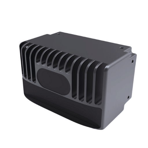
Industrial Sensing Challenges — Why Solid-State LiDAR Replaces Mechanical Sensors
Solid-state LiDAR sensor technology eliminates the single biggest failure point in industrial sensing: mechanical rotation. Traditional mechanical lidar systems rely on spinning mirrors and motors that degrade under vibration, dust, and continuous operation — generating maintenance costs that compound over every deployment year.
Unlike mechanical lidar, a solid-state lidar uses electronic beam steering with no moving parts. The result: longer mean time between failures (MTBF), a sensor body compact enough to mount inside AGV chassis, and field reliability rated to IP65 for dust and water jet exposure.
Three Solid-State Technologies
MEMS (Micro-Electromechanical Systems)
— A micro-mirror oscillates to steer the laser beam. Quasi-solid-state with the best balance of range (50–200 m), angular resolution (0.1–0.3°), and cost. Most commercially mature.
OPA (Optical Phase Array)
– Electronic phase shifters direct the laser beam, no moving parts. True solid state sensor with sub-$100 service units at scale on the horizon and high angular resolution.
Flash LiDAR
– Sends out a broad laser pulse illuminating the entire scene at once and uses a detector array to gather a high-def 3D point cloud snapshot. Short-range high speed solutions (5-30 m).
Each approach addresses different field-of-view and detection range requirements. The right choice depends on your operating environment — whether you need long-range SLAM navigation, close-range obstacle avoidance, or certified safety zone monitoring for human-robot collaboration.
Why the Industry Is Moving to Solid-State
The global solid-state lidar market reached $0.50 billion in 2025 and is projected to grow to $3.20 billion by 2030, reflecting a compound annual growth rate above 30%. This shift is driven by three converging factors: semiconductor manufacturing processes that enable mass production at lower cost, the automotive ADAS industry demanding compact sensors for vehicle integration, and industrial automation projects requiring maintenance-free lidar systems that survive years of continuous operation in dust, vibration, and temperature cycling.
For factory floor deployments — from autonomous mobile robots navigating warehouse aisles to safety laser scanners protecting press brake operators — solid-state lidar technology delivers the reliability that mechanical rotating sensors simply cannot match over 50,000+ operating hours.
QJKH Solid-State LiDAR Product Line — Models, Specs & Selection Guide
Our lidar sensor lineup covers the full application spectrum — from millimeter-precision measurement to SIL 2 safety-certified protection. Every unit ships with Ethernet UDP or RS232 output for direct integration with PLCs, ROS stacks, and industrial controllers.
YB Series — Navigation & Measurement LiDAR
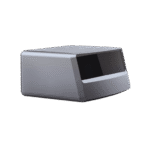
The YB series is a single-line lidar based on the dToF (direct time-of-flight) ranging principle. It delivers 270° scanning coverage with angular resolution as low as 0.1° and detection radius up to 40 m at 70% reflectivity.
- Blind-spot-free design near the sensor window
- Multi-user monitoring (up to 4 simultaneous connections)
- Strong co-source light interference resistance for multi-sensor deployments
- Cross section: 52 mm × 52 mm × 70 mm (fits within small AGV housings)
SH Series — Safety-Certified LiDAR
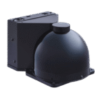
The SH series meets IEC 61496 Type 3 safety requirements with SIL 2 (IEC 61508), Category 3 (ISO 13849), and Performance Level d certification. Designed for AGV safety zones, human-robot collaboration, and access control protection.
- Protection radius: 3 m (SH27-03) or 5 m (SH27-05) at 1.8% reflectivity
- Alarm zone radius: 10–20 m
- 64 static zone groups + 256 dynamic/static zone group configurations
- Dual-mode protection: PAA mode + PP mode for flexible safety deployment
- Window contamination indicator for predictive maintenance
- Millisecond-level strategy switching (< 50 ms delay)
| Model | Detection Radius | Angular Resolution | Output | Best Application |
|---|---|---|---|---|
| YB27-15CE | 15 m | 0.15°@20Hz | Ethernet UDP | Indoor AGV navigation |
| YB27-25CE | 25 m | 0.15°@20Hz | Ethernet UDP | Warehouse SLAM mapping |
| YB27-25HE | 25 m | 0.1°@25Hz | Ethernet UDP | High-precision measurement |
| YB27-40HE | 40 m | 0.1°@25Hz | Ethernet UDP | Large-area monitoring |
| YB27-25HS | 25 m | 0.3°@30Hz | PNP/NPN | Robot obstacle avoidance |
| YB27-25HD | 25 m | Adjustable | Ethernet + PNP | Dual-purpose: measure + avoid |
Solid-State LiDAR vs Mechanical LiDAR — Data-Driven Performance Comparison
Mechanical lidar systems spin at 10–20 Hz with motors, bearings, and optical encoders. While they deliver full 360-degree coverage, this rotation introduces trade-offs in size, weight, power consumption, and long-term reliability that industrial integrators weigh carefully against solid-state alternatives.
| Parameter | Solid-State LiDAR | Mechanical LiDAR |
|---|---|---|
| Moving Parts | None (true SS) or micro-mirror (MEMS) | Motor + bearings + optical encoder |
| Typical Size | 52×52×70 mm (YB series) | 100×100×150 mm typical |
| Weight | ~150–360 g | 500–1200 g |
| Power Consumption | < 3–4 W | 8–15 W typical |
| Field of View | 100°–276° (directional) | 360° (rotating) |
| Angular Resolution | 0.1°–0.5° | 0.1°–0.4° |
| Detection Range | 3–40 m (safety) / 5–200 m (MEMS) | 10–100 m typical |
| MTBF | Higher (no wear parts) | Lower (bearing/motor wear) |
| IP Rating | IP65 standard | IP64–IP67 varies |
| Vibration Resistance | 10–55 Hz, 0.35 mm amplitude | Sensitive to sustained vibration |
| Unit Cost Trend | Declining toward $100–500 | $1,000–20,000+ |
Presents a good choice for AGV progress detection and collision avoidance sensors that are ceiling mounted for full 360 view. For forward object detection and safety zone monitoring directional solid state laser sensors are better suited in terms of weight, size and cost.
Solid-State LiDAR Technology Comparison: MEMS vs OPA vs Flash — 2026 Engineering Reference
| Parameter | MEMS | OPA | Flash |
|---|---|---|---|
| Detection Range | 50–200 m | 10–100 m | 5–30 m |
| Field of View | 60°–120° | 30°–90° | 60°–120° |
| Angular Resolution | 0.1°–0.3° | 0.01°–0.1° | 0.5°–2° |
| Frame Rate | 10–30 fps | 10–100 fps | 30–60 fps |
| Unit Cost (2026) | $200–1,000 | $100–500 (projected) | $50–300 |
| Maturity Level | Commercial | Early commercial | Commercial |
| True Solid-State? | Quasi (micro-mirror moves) | Yes — zero moving parts | Yes — zero moving parts |
| Best Application | Automotive ADAS, long-range AGV | High-precision spatial mapping | Short-range 3D obstacle detection |
MEMS-based lidar currently dominates commercial deployments because it balances range, resolution, and cost better than any alternative. OPA and flash lidar continue advancing toward true solid-state architectures — with OPA promising eventual unit costs below $100 through semiconductor processes, and flash lidar already shipping for short-range 3D obstacle detection in autonomous mobile robots.
Selection Framework: When to Choose Each Type
Choose MEMS
when you need long-range detection (50–200 m) for outdoor AGV navigation or automotive ADAS applications. MEMS delivers the highest resolution at practical cost points.
Choose Flash
when your application requires instantaneous full-scene capture at short range — robotic bin picking, conveyor scanning, or close-proximity safety monitoring where frame rate matters more than distance.
Choose OPA
for emerging high-precision spatial mapping applications where beam agility and ultra-fine angular resolution outweigh current cost premiums.
For most industrial automation use cases — AGV navigation under 40 m, robot obstacle avoidance, and safety zone protection — MEMS-based and dToF sensors offer the best combination of proven reliability, adequate detection range, and manufacturing readiness.
Solid State LiDAR Sensor: Certifications and Safety Compliance
Every QJKH lidar sensor undergoes testing per international safety and electromagnetic compatibility standards at our 1,000+ m² R&D center and laboratory. The facility supports EMC testing, temperature/humidity cycling, vibration/shock testing, and IP protection verification.
IEC 61496
Type 3 ESPEIEC 61508
SIL 2ISO 13849
Cat. 3 / PL dCE Marking
EU ConformityUL 61010-1
Safety StandardEN 60825-1
Laser Safety Class 1EN 61326-1
EMC IndustrialIP65
Dust & Water JetSafety Level Quick Reference
SH Series (Safety LiDAR):
Type 3 (IEC 61496) SIL 2 (IEC 61508) Cat. 3 (ISO 13849) PL d
Solid-state, category 4 classified LiDAR sensor NSE (safety light curtain):
category 4(IEC 6 14 96) SIL 3 (IEC 6 15 08) Cat. 4 (ISO 13849) PL e
EMC Certification
EN 61000-4-2 (E Deaf), EN 61000-4-3 (Electro-magnetic wave radiation), EN 61000-4-4 (Electro-magnetic switch static electricity), EN 61000-4-6 (Interference-coupling) EN 61000-4-8 (DeMagnetic field)
Procurement Guide: Solid-State LiDAR Pricing · Lead Time · OEM Support
Purchasing industrial lidar sensors from a direct manufacturer means fewer markup layers between your engineering team and the production line. We supply importers, distributors, and OEM integrators across 40+ countries with standard and custom-configured units.
Pricing Factors
- Significantly lower Cost for model with longer detection distance (15 mvs40 m) and Ethernetoutput wiring features (Ethernet vs PNP/NPN) and safety qualification level
- Volume discounts commence at 10+ units, with deeper discounts at 100+ and 1000+ units
- OEM customization options – custom firmware, branding, mounting, cabling and interface modifications are quoted separately by project
- FOB Shanghai / CIF to destination port. T/T and L/C methods available
Lead Time & Delivery
- Standard units shipped 15 business days after receipt of order
- OEM and custom models require 30-45 business days, from design review through sample acceptance
- Seeking a tight schedule? Small-batch rush items can ship within 7 days – direct sales inquiry for stock availability
- Subsidized samples available for appropriate projects. Fill out the following form for approval
OEM Customization Process
Specifications
– Specify your required detection distance, FOV, interface, safety level and installation conditionsProposal
– Our engineering team will deliver a technical proposal in 5 business daysSample Approval
— Receive test samples for integration validationManufacture
– Production, batch quality review, and pre shipment testing
Solid-State LiDAR Model Selector
Answer 3 questions to find the right QJKH LiDAR sensor for your application.
Recommended Model
Series
Detection Range
Angular Resolution
Output
Safety Rating
IP Rating
Best For
FAQ — Solid-State LiDAR Sensor Questions
What is a solid-state LiDAR sensor?
A fully solid-state laser-image sensor operates without moving, spinning, or adjusting lenses. The electronic beam steering (via MEMS mirrors, optical phased array, or flash illumination) scans across the scene, creating a 3D point map in real-time. Without moving parts there is less fatigue, wear and tear, and less down-time.
How much does a solid-state LiDAR sensor cost?
Unit pricing depends on detection range, safety certification level, and order quantity. MEMS-based industrial sensors typically range from $200–$1,000 per unit in volume. Flash lidar modules for short-range applications can start below $300. Contact us with your project requirements for a precise quotation.
Who makes solid-state LiDAR sensors?
Top Solid-state laser sensor brands are Hesai, RoboSense, Innoviz, Ouster, Blickfeld. QJKH specializes in industrial safety sensors in China offering IEC 61496 / ISO 13849certified solid-state lidar sensors and OEM customization with direct factory prices.
Solid-state vs mechanical LiDAR — which should I choose?
Opt for solid-state lidar in applications where light weight, miniature, maintenance-free operation is key (AGV navigation, obstacle avoidance, safety zones). Opt for a mechanical scanner only for a single unit that covers 360 degrees (up on roof of vehicle) and must detect an entire environment instantly. For more typical use cases, solid-state will give you a better value-to-buck ratio.
What is the detection range of solid-state LiDAR?
Range varies by technology type. MEMS-based sensors reach 50–200 m. Our YB series covers 15–40 m at 70% reflectivity, which suits most AGV and warehouse applications. The SH safety series provides 3–5 m certified protection radius with 40–60 m measurement capability.
What are MEMS, OPA, and Flash LiDAR?
Common categories of solid-state lidar systems. Electro-magnetic beam steering is done with an OPA or a MEMS mirror. Flash illuminates the entire environment at all angles with a single blink. OPA is due to have the longest detection range because of the full use of beam power. Limits include resolution, beam width, detection speed and operational distance.
Can QJKH provide OEM or custom solid-state LiDAR solutions?
Yes. We provide full OEM service including custom firmware, branding, mounting configurations, and interface modifications. Our engineering team works closely with clients from requirements specification through sample approval to mass production. Typical OEM lead time is 30–45 business days.
What safety certifications do QJKH LiDAR sensors carry?
Our SH safety lidar series is certified to IEC 61496 Type 3, IEC 61508 SIL 2, ISO 13849 Category 3 / Performance Level d. All products carry CE marking and comply with UL 61010-1, EN 60825-1 (laser safety), and EN 61326-1 (EMC). Full test certificates are available upon request.
Trending now