Get in touch with QJKH Company
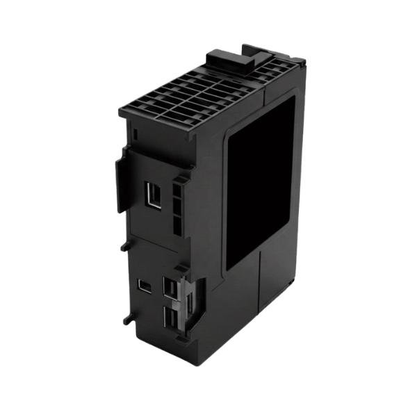
Safety Relay Modules — Dual-Channel, Multi-Function & Expansion Solutions
Dependable machine safety for global OEMs and Distributors -the development center in Hangzhou, certified to global safety standards and stand by committed export team that regards your distribution business as a longterm partner.
Request Free Sample + Quote
Why Standard Relays Fail in Safety-Critical Circuits — And Why Your Distribution Business Needs a Reliable OEM Partner
Safety relay modules are located at the interface between a sensing device – an emergency-stop button, a safety light curtain, a two-hand control, a safety gate – and the contactor that actually removes power from a dangerous machine motion. When that interface fails, the consequences are injury and lost production. A generic electromechanical relay is not capable of holding that interface, and this is the core motivation to provide safety relay modules as a separate product.
The Failure Mode
That form of failure is contact welding. During high-current inductive switching—a 7.5 kW motor contactor, a large solenoid, an arc-generating load—the normally open contacts on a conventional relay can weld together. The coil drops out, the relay is supposed to open, but the welding pinches the contact together and the dangerous motion continues. A conventional relay has no way of knowing that it has failed dangerously and no way of telling the processor which is downstream. That’s the pain.
Root Cause
Mechanically linked contacts missing. In a conventional relay, each contact is free to operate independently. In a force guided relay – the fundamental component of every safety relay module – NO and NC contacts are mechanically forced according to EN 50205. If the NO contact welds closed, the mechanical linkage must physically stop the NC contact opening. A monitoring circuit is used to verify that the NC contact stays in closed position after de-energisation; if it doesn’t, the safety function enters a failsafe state and must be taken out of operation manually.
Architecture & Validation
Resolution ensures that power is only energized when the relay’s two channels are in agreement; CCH Sensing SR-Series modules use a safety relay module with this architecture: two independent relays with force guided contacts, cross-channel diagnostics, monitored start input, and feedback input to detect a welded contactor upstream in the power path. Validation has been performed by a third-party functional safety assessment; every model in the SR-Series has been certified to IEC 61508 and IEC 62061, and is designed to Category 4 architecture (the architecture required for PL e applications) under EN ISO 13849-1.
Distributor-side pain is different — and just as real
Safety engineers buy on risk avoidance. Importers and industrial automation distributors buy on margin, predictability, and depth of supplier relationships. Each week we get the same frustration from partners we interact with in the EU, Southeast Asia, and the Middle East: Tier-1 European brands are designed for the direct-ship model for developed markets: premium unit price, tight distributor margin, inflexible lead-time commitment, and major support processes routed through regional sales offices over factory support. That system didn’t work for a Polish packaging OEM customer of ours who wanted 400 private-label safety relays for a safety cabinet system redesign. CCH was created for the answer to be different.
As a dedicated Chinese manufacturer of industrial safety sensors with more than 20 years of design, manufacturing, and export experience, we serve the importers and automation distributors that incumbent brands have never been structured to serve. Each of our models ships with a documented safety function, third-party assessability, and a procurement path that assumes you are running a distribution business — not an individual customer transaction. Pricing, MOQ, and lead time are summarized below, and technical questions are answered directly by our engineering team instead of routing through three layers of a support queue.
CCH SR-Series Safety Relay Modules — Product Line & Selection Matrix
Our CCH SR-Series models cover the five safety functions that account for the majority of machine safety circuits: emergency stop, safety gate, OSSD light curtain, two-hand control, and multi-function configurable. Every model shares the same internal architecture — dual-channel monitoring with force-guided output contacts — so a distributor stocking five SKUs can offer a safety solution for essentially any application a fabrication shop, packaging line, CNC cell, or robotic integrator will request, instead of committing shelf space to twelve fragmented catalog SKUs.
SR-E Series
E-Stop & Safety Gate
Dual-channel monitoring of emergency switches and tongue-actuated safety gate switches. Automatic or monitored manual start.
- 2× NO safety outputs, 1× NC monitoring output
- 24 V DC input, screw or push-in terminals
- Compact 22.5 mm housing
- Up to SIL 3/PL e / Cat. 4 across individual applications
SR-LC Series
OSSD / Light Curtain
Interface between OSSD-output safety light curtains or laser scanners with all-ups contactors. Safety light curtain/muting/latch delay versions also available
- 2× OSSD inputs, dual safety outputs
- Release delay up to 30 seconds (configurable)
- Cross-monitoring for single-channel fault detection
- Muting function for material pass-through
SR-TH Series
Two-Hand Control
Type IIIC two-hand control per EN 574 for presses, clinching machines, and numerous applications that require concurrent actuation within a 500 ms window.
- Simultaneity monitoring ≤ 500 ms
- Dual NO + dual NC button inputs
- Automatic start, no reset button required
- Suitable for PL e two-hand applications
SR-MF Series
Multi-Function Configurable
Rotary switch for user definable capability of up to four safety functions – emergency stop, safety gate, light curtain, two-hand – in one device – without needing a PC configurator or proprietary software.
- Up to 4 configurable safety functions
- No PC software – mode selection by rotary switch
- Up to 4 enabling current paths
- Push-in connection technology
SR-EX Series
Safety Extension Relays
Contact-expansion modules that extend the output contacts of a pair of SR-Series base modules, or can feed into existing Tier-1 safety controllers already on your customer’s machine.
- 4 to 8 additional enabling current paths
- Cross-brand compatible
- Low-cost stocking unit for distributors
- Force-guided contacts throughout
Cross-Application Safety Relay Selection Matrix
The way we have developed recommendation decision is application type+performance level matched with the preferred model within SR-Series. The application wiring decision trees, single-channel or dual-channel logics, 12 points of safety related circuit designing common errorscan be found in the full PDF document.
| Application | PL d / SIL 2 | PL e / SIL 3 | Channels | Recommended Series |
|---|---|---|---|---|
| Emergency Stop Button | SR-E-1CH | SR-E-2CH | 1 or 2 | SR-E Series |
| Safety Gate Interlock | SR-E-1CH | SR-E-2CH | 2 required | SR-E Series |
| Safety Light Curtain (OSSD) | SR-LC-STD | SR-LC-MUTE | 2 OSSD | SR-LC Series |
| Two-Hand Control Press | — | SR-TH-IIIC | 2 required | SR-TH Series |
| Safety Mat / Edge | SR-MF-STD | SR-MF-STD | 2 | SR-MF Series |
| Robot Cell (multi-function) | SR-MF-STD | SR-MF-4F | 2 | SR-MF Series |
| Contact Expansion | SR-EX-4NO | SR-EX-8NO | — | SR-EX Series |
“Indeed, we elect not to offer the proprietary configurator software for our mult-function series. Distributors we had interviewed told us that free software is effectively not free; that it costs them resourcing as in-house expert and trainer for every single new technician been sent onto installation party planning. Rotary switches, impact clearer identification, and the wiring schematic detail pasted onto housing lid would beat any PC tool the practical in deployments picking the application on the shopping grid.”
Performance Specifications, Standards & Functional Safety Compliance
Safety engineers don’t buy on marketing blurb. They buy on the specification table, the standard numbers and the functional safety assessment on file. This is for them. Every number below is the published specification for the SR-Series reference design; specific model variants have their own datasheets with the exact parameters for that SKU.
| Parameter | SR-E (E-Stop) | SR-LC (Light Curtain) | SR-MF (Multi-Function) | Reference Standard |
|---|---|---|---|---|
| Safety Category | Cat. 4 | Cat. 4 | Cat. 4 | EN ISO 13849-1 |
| Performance Level | PL e | PL e | PL e | EN ISO 13849-1 |
| SIL Capability | SIL 3 | SIL 3 | SIL 3 | IEC 61508 / IEC 62061 |
| Input Channels | 1 or 2 (selectable) | 2 × OSSD | 1 or 2 (per function) | — |
| Response Time | typical 10–30 ms | typical 15–35 ms | typical 20–40 ms | IEC 61508 |
| Safety Outputs | 2 NO + 1 NC monitor | 2 NO + 1 NC monitor | up to 4 NO | — |
| Output Rating | 6 A / 250 V AC (resistive) | 6 A / 250 V AC | 6 A / 250 V AC | EN 60947-5-1 |
| Input Voltage | 24 V DC | 24 V DC | 24 V DC | — |
| Terminal Type | screw or push-in | screw or push-in | screw or push-in | — |
| Housing Width | 22.5 mm | 22.5 mm | 45 mm | DIN rail EN 60715 |
| Ambient Temperature | −25 to +55 °C | −25 to +55 °C | −25 to +55 °C | IEC 60068 |
| Contact Design | force-guided (positively driven) | force-guided | force-guided | EN 50205 |
How to read Performance Level and SIL together
Relationship between PL (under EN ISO 13849-1) and SIL (under IEC 62061 and IEC 61508) is what most often trips people up on buying calls. PL e under EN ISO 13849-1 maps roughly to SIL 3 under IEC 62061 for discrete safety relay applications; that mapping is approximate because the two standards compute the rating differently. EN ISO 13849-1 considers MTTFd, diagnostic coverage and common-cause failures on a per-channel basis then translates that into Category 1 to 4 and then on to PL a-e. IEC 62061 takes the probability of dangerous failure per hour (PFH) and aggregates the entire safety function as a whole.
This causes confusion when ordering a machine into the European market, because the safety integrator will usually choose the standard that suits the customer’s own documentation – older installations will refer to 13849, while newer, more complex electronic safety systems will prefer 62061. Every safety integrity fitting Siemens SR-Series modules provides the relevant data in a generic format so the customer’s documentation can always be accurate, no matter which standard they refer to.
Dual-channel versus single-channel — the decision that is never negotiable for PL e
For every PL e application, the input monitoring must be dual-channel. If, under the hazard analysis in ISO 12100, you conclude that a single failure must be tolerated – meaning the first fault must not cause the safety function to be lost – dual-channel is no longer optional; it is mandatory. Every Siemens SR-Series supports both circuit wiring modes – single-channel where the risk assessment suggests it is safe, or dual-channel with cross-monitoring where it isn’t. Channel count is decide at the wiring terminal level, not as a separate SKU, making the selected inventory mix easier.
CCH SR-Series in a Fragmented Safety Relay Market — Specification, TCO, and Distribution Fit
There is a mistaken belief that the safety relay market is stacked with just two or three European brands. This is simply wrong. Talk to anyone on any active automation forum or discussion group and they will list eight or more brands as primary candidates – Phoenix Contact, Pilz, Allen-Bradley Guardmaster, Omron, Schmersal, Dold, IDEM, Banner, Sick, ABB, ReeR – and what’s affecting the buy is never brand loyalty. It’s fit: how well does the product match the application, is the integration path understood and does it scale with the dealer’s core business model.
CCH Sensing doesn’t come to snatch Pilz’s crown. PNOZ is a brand more than a third of a century old, and the PNOZsigma line is an outstanding product. What we do, unlike Pilz, is bring a business solution to distributor dealers the Tier 1 brands have never aimed for. Our Table below is optimally shaped around distribution fit, in marketing terms, not sales promotion bullets.
| Dimension | Tier-1 European Brands | US Distribution Catalog Brands | CCH SR-Series |
|---|---|---|---|
| Functional Safety Rating | Up to SIL 3 / PL e | Up to SIL 3 / PL e | Up to SIL 3 / PL e |
| Force-Guided Contacts | Yes (EN 50205) | Yes (EN 50205) | Yes (EN 50205) |
| Unit Street Price (dual-channel E-Stop reference) | premium tier (Pilz PNOZ X2.8P verified $356–$387 on secondary market) | mid tier ($120–$250 range) | value tier (contact for distributor quotation) |
| Pricing Transparency on Vendor Site | opaque (quote only) | specific list pricing | range disclosure + Request Quote |
| OEM / ODM / Private Label | generally no | no (distribution model) | yes (core service) |
| Distributor-Focused Portal | limited (sales office routing) | end-customer e-commerce | dedicated export team |
| MOQ for Private Label | case-by-case | n/a | distributor tier — contact for quotation |
| Lead Time (standard models) | next-day from regional stock | next-day from regional stock | typical range from factory — contact for current lead time |
| Configurator / Software | proprietary (PC tool, vendor login) | n/a | rotary switch — no software required |
| Test Report Access | sales-gated | datasheet only | TÜV cert + test report on request under NDA |
5-Year Total Cost of Ownership — What Actually Moves the Number
There is no standard 5-year TCO study available in the market for safety relay modules, any supplier quoting you a single “we will save you 40%” headline is merely inflating the figure to impress, not to be accurate. A realistic approach would be to identify the cost drivers and let your purchasing team run the true volumes. The factors below are those that determine the TCO delta between a Tier-1 European brand and CCH for your typical distribution business.
Unit Price
Dominant cost factor at year 0. Tier-1 premium, CCH value tier — but unit price is only 50-60% of TCO over 5 years.
Freight & Customs
Air freight option for expedited replacement, sea freight for bulk stocking. Adds meaningful cost at low volumes, marginal at pallet volumes.
Field Return Rate
Factory-direct warranty replacement reduces the distributor’s own exposure; return shipping paid on validated defects.
Certification Ongoing
Annual re-audit cost only if your customer’s market standard requires it; most functional safety assessments are valid 3-5 years.
Private Label Setup
One-time engineering and labeling cost, amortized across production runs — CCH standard for distributor partners, Tier-1 rare.
Stocking Depth
SR-Series uses a simplified 5-SKU stocking strategy that matches distributor cash-flow models better than a 100-SKU catalog.
Applications, Real Deployments & Field Results
Our SR-Series is implemented throughout packaging equipment, CNC machining centers, robotic welding stations, conveyor E-stop zones, and automation assembly lines. Instead of listing industry directory, what is below is a few representative deployments with our distributor partners spanning 2024–2025. Customer identities are NDA+consumer were masked, results are aggregated.
Packaging Machinery · Southeast Asia
50-line flowpack packaging OEM
Moved from a three-brand twelve-SKU mixed-vendor safety relay stock to a five-SKU stocking plan for CCH SR-Series. Distributor indicated no safety relay warranty claims over 18-months of field use, and the simplified stocking significantly reduced inventory carrying costs for distributor. [Case validated under NDA with distributor partner]
Metal Fabrication · Eastern Europe
Press-brake two-hand control retrofit
Retrofitting 24 older press brakes with the SR-TH Series two hand control modules to get the fleet up to date with a refeshed functional safety assessment. The integration was performed in less than four weeks per machine by the customer’s own maintenance team using only printed wiring diagrams- no vendor configurator integration enabled much faster turnaround time. [Integration time provided by distributor partner]
Robotic Welding · Middle East
Robot cell fence interlock + light curtain
A new robotic welding cell was installed and distributor supplied SR-LC and SR-E modules. The integrator exclusive supplier had adopted a Tier-1 European nameplate, but used dual sourcing to reduce lead-time uncertainty. SR-Series was specified as an alternate supplier (distributor private label) with no re-engineering, and passed customer’s functional safety audit on the first attempt. [distributor observed audit outcome]
CNC Machining · Latin America
Multi-function safety cabinet standardization
CNC machine tool OEM adopted SR- MF Series multi-function modules for whole product line from E-stops, safety gates to light curtains. One SKU per application reduced OEM’s spare parts burden for safety circuit replacements and minimized OEM’s technician training overhead for safety circuit replacements. [Case validated with distributor NDA]
The China Safety Component Trust Gap — Addressed Directly
There is a belief that ‘CE’ markings on a Chinese component means ‘China Export’ and not ‘Conformit Europenne’. That meme persists because the concern is legitimate. There are documented cases of inferior Chinese consumer electronics shipping with weaselly produced or pseudo-declared CE documentation, and safety engineers who read about those episodes carry the finger-wagging into every procurement discussion that involves a Chinese supplier. Ignoring that concern would be dishonest, and dishonesty is just not the CCH Way.
Here’s how CCH mitigates that fear in practice, not in marketing prose:
Independent third-party functional safety verification.
SR-Series models are assessed at an accredited functional safety laboratory, not self-declared. Each assessment report includes the PFHd calculation, the MTTFd per channel, the diagnostic coverage figure, and the Category/PL/SIL assignment. Each report is made available to distributor Partners upon request under an NDA – not because the data is proprietary, but because the client identities within it are.
Verification pathways for approvals.
TV certification numbers printed on each datasheet can be verified directly on the certifying body’s online database. If a distributor wishes to audit the verification process, we provide the certification number, the certifying body’s contact details, and the fields to search within their database record. No blind trust needed – just a web browser.
Traceable production runs.
An individual SR-Series module includes a product batch identification code. If the field reports a fault, we can trace it back to a specific production run and isolate the effected batch should a systemic issue arise. This is not hype – it is the ISO 9001 QMS standard operating procedure under which CCH is working.
Production facility inspection invite.
Distributor Partners may visit the CCH factory in the Hangzhou Airport Economic Demonstration Zone. This is not a display room – this is the assembly line where SR-Series modules are constructed. We prefer that distributors visit prior to a first large purchase, because it is the easiest way to abolish the trust chasm.
Distributor Partner references.
On request, we provide three to five active Distributor Partners who have fielded CCH safety components in their range of products within the last two years. Those Partners speak honestly – not coached – and are introduced with their explicit consent.
Certifications, OEM / ODM Capability & Global Export
All of the SR-Series models have the certifications required for their targeted machine safety applications. Individual model certification lists are published on each datasheet; notated certifications are listed below.
TÜV — Functional Safety Assessment
CE — EMC + LVD
CCC — China Compulsory
RoHS & REACH
ISO 9001 QMS
OEM and ODM process for distributor partners
CCH manages OEM & ODM projects across four distinct phases, which are supervised by a single factory engineering contact from beginning to end – meaning no sales to engineering handoff that results in unnecessary delays.
01
Specification review
The distributor sends us the application definition, required performance criteria, private label specs, packaging specifications, and document language requirements. Our engineering team identifies which SR-Series SKU is best suited for the application and what changes, if any, need to be made.
02
Sample and validation
A free sample batch is shipped using the private label configuration confirmed with the distributor in the previous step. The end-user uses the functional safety documentation to validate the sample for their application and returns correction requests.
03
Production order
Following sample validation, the production order is queued for scheduling. The distributor receives weekly update schedules when the production order reaches the shipment milestone.
04
Shipping and after-sale
Factory ships FOB Shanghai or CIF Available upon negotiation, air freight is available for urgent replacements. After-sale service is immediate direct engineering team contact, not a Ticket Queue.
Pricing Factors, MOQ, Lead Time & Payment Terms
Pricing for the safety relay modules is driven by specification and volume. We aren't going to post a list price that survives the first sourcing conversation. Instead, we list the factors that contribute to the final factory quote. For a specific number, contact us with your application definition, targeted volume, and private label needs.
Factors that shape SR-Series distributor pricing
Model series
SR-E and SR-EX are the most cost-efficient entry points. SR-MF multi-function commands a premium over the single-function models for the same rated performance level.
Annual volume
Quantity breaks start at distributor-tier pricing and scale down at OEM-tier volumes. Private-label runs are quoted separately from catalog-label stock.
Private label and packaging
Distributor branding, custom packaging, and localized documentation are quoted as a one-time engineering fee plus per-unit markup amortized over the production run.
Certification scope
Standard SR-Series carries TÜV, CE, and CCC. If your end-market requires additional certifications (UL, UKCA, EAC), those certification paths are quoted separately with the lead time required for the assessment.
Shipping term
FOB Shanghai is the standard distributor term. CIF to destination port is negotiable. Air freight is quoted for urgent replacement orders and expedite requirements.
Payment terms
Standard terms are 30% T/T deposit with balance before shipment. Letter of credit at sight is available for orders above a threshold volume. Established distributor partners may negotiate longer terms after relationship history is built.
Engineering & Procurement Tools
Access our suite of interactive utilities designed to streamline your safety relay selection, evaluate financial impacts, and simplify standards compliance.
Ready to Evaluate the SR-Series for Your Distribution Portfolio?
Ask for a sample, a price quote for a reliable distributor, and the name of a representative inside the engineering department. This is the front-line point of contact, not a customer service routing desk.
Request Free Sample + QuoteFrequently Asked Questions
A generic relay has no mechanical linkage between its independent NO and NC contacts. Should those contacts damage weld shut during a high-current switching event a common canonical failure mode , the relay cannot notify the downstream contactor and its failure to turn off reliably. A safety relay module uses two redundant channels with force-guided contacts specified per EN 50205, cross channel diagnostics, and a feedback input that ensures the downstream contactor is off as a safety function. When a safety fault occurs the safety relay falls into a fault state and must be manually reset. A generic relay module is not required to fall into a safe state in all fault conditions.
The Our SR-Series rating is the result of a third-party functional safety certification by an accredited laboratory, not by self-determination. Every certification report cites PFHd, channel-by-channel MTTFd, diagnostic coverage, and the Category / PL / SIL designation. TV certificate numbers are printed on the datasheets and can be verified directly on the certifying body's public database. Distributor partners are welcome to request the full certification report under NDA. If your application cannot easily be confirmed from the datasheet documentation, our engineering team can provide the certification body and certificate number.
MOQ is driven by your level of required customization. Standard SR-Series catalog label stock is available at distributor-tier pricing with moderate quantity discounts. Private label with custom branding and packaging is available for an MOQ that is tied to the tooling and label effort. Complete OEM modifications - custom terminal layout, custom input voltage, non-standard certification - have an MOQ that is determined by the additional tooling and validation effort. Supply us with your application and projected annual volume and we will provide you a unit price with the MOQ in the same reply.
Every SR-Series module has a factory warranty against defect in material and workmanship, validated units will be repaired under warranty with a no-charge shipping back to the end customer. In addition, we will ship a free replacement module under our standard factory warranty terms and conditions. Returns are processed by the same engineering team that serviced the end customer, maintaining technical communication and consistency. We have an effective OEM and distribution direct support system that allows us to track batch production and customer service to ensure our products are reliable, and to bring attention and fix any batch recalls that might arise.
Yes, in most common integration scenarios; our SR-EX series expansion relays, and the original, standard SR-E series can accept OSSD outputs from any Tier-1 safety controllers and provide force-guided contact expansion at a price point friendly to any distributor. Signal-level integration is easy because we all follow the same standards- IEC 61508, IEC 62061, and EN ISO 13849-1; but where integration may get more complex is if the Tier-1 vendor deploys a proprietary bus protocol instead of simple discrete safety IO. In that instance the SR-Series is not the device for you, and we will tell you factually if that is the case.
Standard payment terms are 30% T/T advance and 70% prior to shipment; larger orders can take advantage of bank-backed letters of credit at sight. Distributor relationships can secure extension on terms once purchase history proves yourself; FOB Shanghai, netist, point-to-point depends on your primary vessel and destinations; C&F, CIF are options. Expedited shipping is available for emergency end-of-line replacement requirements. Customer care quality is provided directly by the engineering team - your primary contact is your follow-up contact and will be your replacement contact; no ticketing systems or routing ports.
Trending now