Robot Cell Safety · Access + Area Safeguarding

Robot Cell Safety with Light Curtains & Laser Scanners

Safeguard industrial robot cells by matching the protective method to the actual hazard and access path. ENT Type 4 safety light curtains can protect defined access openings, while SH27 safety laser scanners provide configurable 2D protective-field monitoring for suitable robot-cell areas. Fixed and interlocked guarding can remain an essential part of the complete safeguarding strategy.

Type 4
ENT Safety Light Curtain
14 / 25 / 45 mm
ENT Detection Options
3 m / 5 m
SH27 Protective Range
276°
SH27 Scanning Angle
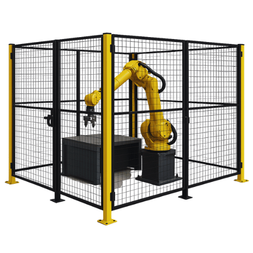
Industrial robot cell with perimeter guarding for robot cell safety
Fixed Guarding
Physical perimeter
ENT
Defined access opening
SH27
2D area monitoring
Different safeguards perform different roles inside the complete robot-cell safety concept.
Selection Principle

Start from the robot hazard, personnel access path, stopping performance, required safety function and cell geometry before deciding whether the application needs a safety light curtain, safety laser scanner, physical guard, interlocked access or a combination of safeguarding measures.

02 · Robot Cell Hazards & Access

Identify the Robot Hazard and Every Personnel Access Path

Robot cell safeguarding should begin with the complete work area rather than with a single sensor. Consider robot motion, tooling, workpieces, peripheral equipment and every foreseeable way personnel can enter or reach into the hazardous area.

Core Principle

Protect the personnel access path to the hazard, not simply the visible robot perimeter. One robot cell can require physical guards, monitored openings and area protection to address different access routes.

01

Robot Working Envelope

The robot arm, end effector and carried workpiece can create impact, crushing, trapping and shearing hazards throughout the reachable operating area.

The hazard assessment should include robot motion together with the process being performed, not only the robot body itself.

02

Operator Loading & Access Openings

Part loading, unloading, inspection and other repetitive tasks can require personnel to approach an open section of the robot cell.

A defined opening can be a potential application for a safety light curtain where the complete safety function and access geometry make electro-sensitive protection suitable.

03

Side & Rear Perimeter

Areas that do not require routine operator access can often be physically restricted with fixed guarding or other suitable perimeter safeguards.

An open front access point does not remove the need to consider side, rear and bypass routes.

04

Maintenance & Teach Access

Setup, teaching, maintenance, troubleshooting and recovery tasks can expose personnel to hazards that are different from normal automatic production.

These operating conditions should be considered separately when defining the robot cell safety strategy.

05

Peripheral Equipment & Process Hazards

Weld guns, grippers, fixtures, conveyors, positioners, presses and other cell equipment can create hazards independent of the robot movement.

Safeguarding should therefore address the complete robot application, not only the robot arm.

Look at How a Person Can Enter, Reach Into or Remain Inside the Cell

Different access patterns can require different safeguarding measures. Before selecting ENT or SH27, define how personnel interact with the cell during production, setup, intervention and maintenance.

01
Reach-In Access
Hands or arms can enter an opening while the person’s body remains outside the cell.
02
Walk-In Access
A person can pass completely through an opening and enter the safeguarded robot area.
03
Service Access
Maintenance or setup personnel may enter locations that operators do not normally use in automatic production.
04
Bypass Access
Consider whether a person can reach over, under, around or through the intended safeguard.
Full-Body Entry

If a person can cross a protective device and remain inside the robot cell, restoring the sensing field does not prove that the safeguarded area is empty. The complete safety design must address personnel presence, reset / restart behaviour and prevention of unexpected hazardous motion.

Physical Boundary

Fixed / Interlocked Guarding

Useful for restricting personnel access around portions of the robot cell where routine open access is not required.

Defined Opening

Safety Light Curtain

Can monitor a defined access plane where personnel must approach an open robot-cell entry point and electro-sensitive protection is suitable.

Monitored Area

Safety Laser Scanner

Can create configurable two-dimensional protective fields for suitable floor-level or area-monitoring applications around the robot cell.

The robot type does not determine the safeguard by itself.

Welding robots, handling robots, palletizing robots and collaborative robot applications can all have different access patterns and process hazards. The appropriate solution depends on the actual application, personnel interaction, stopping performance, cell geometry and required safety function.

03 · Safeguarding Methods

Fixed Guards, Safety Light Curtains and Laser Scanners Perform Different Roles

Robot cell guarding is rarely a question of choosing one protective device for the entire application. Physical guards, safety light curtains and safety laser scanners address different access conditions and can be used together as part of the complete robot-cell safeguarding strategy.

Selection Principle

Choose the safeguarding method from how personnel can reach the hazard and what protective function is required — not simply from the fact that the machine contains an industrial robot.

Physical Perimeter

Fixed & Interlocked Guarding

Creates a physical boundary around areas where unrestricted personnel access is not required.

Physical robot cell guarding can prevent or restrict access around the robot working area and process equipment. It is often an important part of the perimeter even when electro-sensitive protective devices are used at selected openings.

Typical Role
Side and rear robot-cell perimeter
Areas not requiring frequent operator access
Restricting bypass routes around monitored openings
Controlled access through appropriately designed interlocked doors or gates
Defined Access Plane

ENT Type 4 Safety Light Curtains

Monitors a defined access opening without creating a physical barrier across the protected plane.

A safety light curtain can be suitable where personnel need regular access through a defined robot-cell opening and interruption of the protective field is integrated into the required safety function.

ENT models provide 14 mm, 25 mm and 45 mm detection capability options for different safeguarding requirements.

Typical Role
Operator loading and unloading opening
Defined front access to a robot workstation
Reach-in or personnel access where the selected configuration is suitable
Applications where physical doors would unnecessarily interrupt frequent normal access
View ENT Safety Light Curtains →
Configurable 2D Area

SH27 Safety Laser Scanners

Monitors configurable two-dimensional protective fields around suitable robot-cell access and floor areas.

A safety laser scanner can be useful where a flexible protective area is more suitable than a single vertical detection plane. SH27 models provide 3 m or 5 m safety-related protective range and a 276° scanning angle.

Typical Role
Floor-level area monitoring
Wide or irregular access areas
Configurable protective-field geometry
Applications where one fixed vertical sensing plane does not fit the required monitored area
View SH27 Safety Laser Scanners →
Quick Comparison

Match the Safeguard to the Access Geometry

The table below is a practical starting point. Final suitability depends on the complete robot application and required safety function.

Safeguard Primary Role Monitored Geometry Typical Robot Cell Use
Fixed / Interlocked Guard Physically restrict access Physical perimeter or controlled gate Side / rear cell boundary and controlled entry
ENT Safety Light Curtain Detect crossing of a defined opening Vertical or otherwise engineered sensing plane Operator access, loading and unloading opening
SH27 Safety Laser Scanner Detect entry into a configurable protective area Two-dimensional scanned field Floor-level access or wider configurable monitored areas
Combination Safeguarding

One Robot Cell Can Use More Than One Safeguarding Method

A practical robot-cell safety concept can use different protective measures for different parts of the same machine area.

01
Physical Perimeter
Fixed or interlocked guarding restricts access around portions of the robot cell.
+
02
Monitored Opening
ENT can monitor a defined operator access opening where light curtain protection is suitable.
+
03
Monitored Area
SH27 can monitor a configured two-dimensional area where scanner protection fits the access geometry.
SH27 Field Boundary

For SH27 applications, distinguish between the safety-related protective field and any warning field used for non-safety signalling or pre-warning. A warning field should not be presented as a substitute for the safety protective field.

Do not replace one safeguard with another only for convenience.

A fence, light curtain and laser scanner do not perform identical functions. Selection should be based on hazard access, required protective function, stopping performance, installation geometry and the complete safety-related control design.

04 · Safety Light Curtains

ENT Safety Light Curtains for Robot Cell Access Guarding

Safety light curtains can protect a defined robot-cell access opening where operators need regular interaction without a permanent physical barrier across that opening. The correct ENT configuration should be selected from the required detection capability, protection height, access geometry and complete safety function.

ENT Application Role

ENT creates a defined electro-sensitive detection plane across an opening. When that field is interrupted, its safety-related outputs must be integrated into the robot-cell safety control so the required safe machine response is achieved.

Type 4
Safety Light Curtain
Protective-device classification for the ENT series.
14 / 25 / 45 mm
Detection Capability Options
Select according to the required detection function and access geometry.
Up to 1,960 mm
Protection Height
Supports a wide range of robot-cell opening heights.
6.0–30.8 ms
Model-Dependent Response
Use the actual selected configuration when evaluating the safety function.

Where a Safety Light Curtain Can Fit in a Robot Cell

These are common application patterns rather than automatic product selections. Final suitability depends on the robot application and complete safeguarding design.

01

Operator Loading & Unloading Opening

Where an operator repeatedly approaches a defined opening to load, unload or inspect parts, an ENT safety light curtain can monitor crossing of the access plane when the safety concept permits this type of protective device.

02

Robot Workstation Front Access

A vertical light curtain can provide robot cell access guarding at an open workstation where the required protected height and separation from the hazard can be achieved.

03

Reach-In Access to a Defined Process Area

Where only part of the body can reach toward the hazard through a controlled opening, the detection capability and safeguard position should be selected from the actual reach-in condition.

04

Access Combined With Physical Perimeter Guarding

ENT can be used at a selected open access point while fixed or interlocked guarding restricts side, rear and other routes around the robot cell.

ENT Selection

Do Not Choose 14, 25 or 45 mm From the Robot Type Alone

A welding robot, handling robot or assembly robot does not automatically determine light-curtain resolution. Detection capability should follow the body part or access condition that the protective function must detect.

14 mm
Fine Detection Capability
Can be considered where the safety function requires detection of smaller hand or finger intrusion. Final suitability still depends on access geometry and safeguard positioning.
25 mm
Medium Detection Capability
Can be used for applicable hand or arm access conditions where the selected detection capability and required safeguard position fit the design.
45 mm
Larger Detection Capability
Suitable only where the required protective function permits a larger detection capability. It should not automatically replace finer detection simply because the robot-cell opening is larger.

Four Questions Before Positioning the Light Curtain

Robot cell safety light curtain selection is not complete when the model number is chosen. The installer must also verify how the hazard can be reached and whether the required safe machine response occurs before personnel can reach it.

01
What Must Be Detected?
Define the hand, arm or personnel access condition the protective function must detect.
02
Where Is the Hazard?
Consider robot motion, tooling, workpieces and process equipment inside the cell.
03
How Fast Is the Safe Response?
Use the complete safety-function and machine stopping performance, not only the ENT response time.
04
Can the Field Be Bypassed?
Evaluate foreseeable reaching over, under, around or through the protected opening.
Walk-In Robot Cells

If a person can completely cross the ENT protective field and remain inside the robot cell, the light curtain alone does not confirm whether anyone remains in the safeguarded area after the field becomes clear. The complete safety concept must address full-body entry, reset / restart behaviour and prevention of unexpected hazardous motion.

Light curtain position must be evaluated from the complete safety function.
For applicable ISO-based applications, safeguard positioning should consider the actual access geometry, ENT response, downstream safety-control response and machine stopping performance according to the applicable requirements.
Safety Distance Calculator →
Explore ENT Type 4 Safety Light Curtains
Compare available detection capability, protection height and response-time configurations for robot cell access safeguarding and other industrial machine safety applications.
View ENT Safety Light Curtains →
05 · Safety Laser Scanners

SH27 Safety Laser Scanners for Robot Cell Area Monitoring

A safety laser scanner can protect a configurable two-dimensional area where a single light-curtain plane does not match the required access geometry. SH27 safety laser scanners are designed for safety-related protective-field monitoring around suitable robot-cell access and floor areas.

SH27 Application Role

SH27 creates a configurable 2D protective field. Interruption of the safety-related protective field must be integrated into the robot-cell safety control so that the required safe machine response occurs before personnel can reach the hazard.

3 m / 5 m
Protective Range
Safety-related protective distance depends on the selected SH27 model.
276°
Scanning Angle
Wide two-dimensional scanning field for configurable monitoring geometry.
Up to 64
Configurable Zone Sets
Supports multiple configured field sets for suitable machine applications.
100–567 ms
Configurable Response
Use the actual configured response time when evaluating the complete safety function.

Where a Safety Laser Scanner Can Fit in a Robot Cell

SH27 is most useful where the robot-cell safety function requires a configurable monitored area rather than only a fixed access plane.

01

Floor-Level Access Monitoring

A safety laser scanner can monitor a horizontal protective area in front of or around an accessible robot-cell opening where the installation geometry supports this type of safeguarding.

02

Wide Robot Cell Access Areas

Where the access area is wider than a simple doorway or operator opening, a configurable scanner field can provide robot cell area monitoring matched to the required floor geometry.

03

Irregular Protective-Field Geometry

Configurable fields can be shaped around suitable machine boundaries and access geometry where a rectangular vertical light-curtain plane would not fit the required monitored area.

04

Access Combined With Perimeter Guarding

SH27 can monitor an open floor-level access area while fixed or interlocked guarding restricts other routes around the robot cell. The measures perform complementary functions.

Light Curtain vs Laser Scanner

The Difference Is Mainly the Required Monitoring Geometry

Both devices can form part of robot-cell personnel safeguarding, but they monitor different types of access geometry.

ENT

Defined Detection Plane

A safety light curtain is useful when the safety function needs to detect crossing of a defined opening or access plane.

Typical examples include operator loading openings and defined front access to a robot workstation.

SH27

Configurable Two-Dimensional Area

A safety laser scanner is useful when the safety function needs to monitor a configured horizontal or floor-level area.

Typical examples include wide access areas or locations where the monitored shape must follow the cell geometry.

Protective-Field Design

The Scanner Field Should Be Designed From the Actual Robot Cell

A large scanning range does not mean the entire available range should automatically be used as one safety zone. Protective-field design should reflect the actual hazard, approach path and stopping performance.

01
Hazard Location
Identify the robot, tooling, process and peripheral hazards that personnel can approach.
02
Approach Direction
Determine how personnel can enter the monitored area and progress toward the hazard.
03
Complete Response Time
Include the configured scanner response together with downstream safety-control and machine stopping performance as applicable.
04
Field Geometry
Configure the protective area so foreseeable access routes are addressed by the complete safeguarding design.
Protective vs Warning Field

The SH27 safety-related protective field and its warning field do not perform the same function. A warning field can be used for non-safety signalling or pre-warning, but it should not be represented as a substitute for the safety-related protective field.

Four Installation Questions Before Using a Scanner Around a Robot Cell

Scanner selection is only part of the design. The installed protective field must fit the actual floor geometry, personnel approach and complete robot-cell stopping behaviour.

01
Scan Plane
Confirm the scanner position and scan plane detect the intended personnel access condition.
02
Protective Distance
Determine the required field boundary using applicable safeguarding requirements and actual stopping performance.
03
Bypass Routes
Check whether personnel can step around, reach beyond or otherwise bypass the intended protective area.
04
Cell Obstacles
Consider machine structures, fixtures and other objects that can affect the usable scanning field.
Scanner Visibility

Fixed structures, fixtures or other objects inside the scanning plane can create areas the scanner cannot directly monitor. The complete layout should be reviewed so that unmonitored access behind obstacles does not undermine the intended protective function.

Explore SH27 Safety Laser Scanners
Compare protective range, configurable field sets, response options and interfaces for robot cell area monitoring and other industrial safety applications.
View SH27 Safety Laser Scanners →
06 · Safety Control Integration

Integrate Safety Sensors Into the Complete Robot Cell Safety Control

A safety light curtain or safety laser scanner detects access to a hazardous area, but detection alone does not complete the robot-cell safety function. The protective-device outputs must be integrated through appropriate safety logic into the robot and cell control so that the required safe response is achieved.

System Principle

ENT and SH27 are protective input devices. They should not be described as independently stopping the robot or determining when the robot may restart. Those functions belong to the complete validated robot-cell safety architecture.

Typical Robot Cell Safety Signal Path

Detection → Safety Logic → Robot / Cell Control → Safe Response

The exact architecture varies with the robot system, peripheral equipment and required safety functions, but the protective device must be integrated as part of the complete safety-related control chain.

01
ENT or SH27
Detects interruption of the defined protective plane or configured safety-related protective field.
02
Safety Logic
A suitable safety relay, safety PLC, safety controller or other safety-related logic processes the protective-device signals.
03
Robot / Cell Safety Control
The robot controller and relevant machine-control elements execute the safety response defined for the application.
04
Required Safe Response
Hazardous robot or cell movement reaches the state required by the validated safety function.
Simple Safety Interface

Safety Relay

A safety relay can provide an appropriate interface in applications where its functions, input / output configuration and electrical characteristics match the required safety architecture.

It should not be assumed that every robot cell can or should use the same relay configuration.

Multi-Function Cell Control

Safety PLC / Safety Controller

More complex robot cells can involve multiple protective devices, gates, operating modes, peripheral machines and safety functions. A programmable safety controller may be used where the application requires that level of safety logic.

Robot System

Robot Safety Controller

Many industrial robot systems provide safety-related interfaces or functions within the robot control platform. External safeguarding devices must be integrated according to the robot manufacturer’s safety interface and the complete cell design.

Protective Inputs

ENT and SH27 Detect Different Access Conditions

The downstream safety logic can be part of the same robot-cell control architecture, but the two protective devices monitor different physical conditions.

ENT Safety Light Curtain

Crossing a Defined Detection Plane

ENT provides protective-device status when the configured light curtain field is interrupted. The robot-cell safety control then uses that safety-related input according to the required application logic.

SH27 Safety Laser Scanner

Entry Into a Configured Protective Area

SH27 provides the safety-related status associated with its configured protective field. Any warning-field signal remains a separate non-safety function and should not be substituted for the protective field in the safety chain.

System Design Questions

Define the Required Safe Response Before Finalizing the Wiring

The correct response is application-specific. It depends on the robot, tooling, process equipment, operating mode and hazards present in the complete cell.

01
What Hazard Must Respond?
Robot motion, tooling, fixtures and peripheral equipment may all contribute to the hazard.
02
Which Protective Device Triggered?
Define how each light curtain, scanner, gate or other safety input affects the required cell response.
03
What Must Reach a Safe State?
Consider all hazardous equipment affected by personnel entry, not only the robot arm.
04
How Is the Function Validated?
Verify wiring, logic, response, stopping performance and fault behaviour under actual installed conditions.
Reset & Restart

A clear light curtain or scanner field should not be interpreted as proof that the robot cell is empty or as an automatic command for hazardous motion to resume. The validated robot-cell safety design must define the required reset and restart behaviour, particularly where full-body entry is possible.

Sensor response time is only one part of the complete safety-function timing.

Safeguard positioning and protective-field design should consider the response of the selected ENT or configured SH27 together with downstream safety-control response and the actual stopping performance of the robot and relevant cell equipment as required by the applicable safety design.

Safety Relay Modules for Suitable Control Interfaces
CCH safety relay modules can be considered where their functions and electrical characteristics fit the required robot-cell safety architecture. Complex cells may instead require a safety PLC, dedicated safety controller or robot-specific safety interface.
View Safety Relay Modules →
Protective-device ratings do not define the complete robot cell safety performance.

The required safety performance belongs to the complete safety function, including protective devices, safety logic, robot and machine interfaces, output elements, wiring, stopping behaviour and validation. Component specifications should therefore be treated as inputs to the overall robot-cell safety design.

07 · Robot Cell Applications

Robot Cell Safeguarding Across Different Industrial Applications

Robot cells can perform welding, machine tending, material handling, palletizing, assembly and collaborative tasks, but the application name alone does not determine the correct safeguard. Each cell should be evaluated from its actual hazardous motion, process equipment, personnel access and required safe response.

Application Principle

Two robot cells using the same robot model can require different guarding, safety light curtains, laser scanner fields and safety-control strategies because their processes and personnel interactions are different.

01
Automotive & Fabrication

Automotive Welding Robot Cells

Welding robot cells can combine rapid robot motion with weld guns, fixtures, positioners and moving workpieces. Depending on the welding process, additional hazards can include heat, sparks, spatter and radiation.

The safeguarding concept should therefore address both personnel access to the robot working area and the hazards created by the welding process itself.

Access Question
Where do operators enter or reach into the cell?
Consider loading stations, inspection points, gates and service access.
Process Question
What hazards exist beyond robot motion?
Welding equipment, fixtures and process hazards may require additional protective measures.
Safeguarding Measures to Evaluate
Fixed / Interlocked Guarding ENT Access Guarding SH27 Area Monitoring
02
Automated Production

Machine Tending & Operator Loading Stations

Robots are frequently integrated with CNC machines, presses, assembly equipment and other automated production systems for part loading, unloading and transfer.

The safeguarding design must consider both the robot and the connected machine hazards, together with the opening through which operators access the station.

Defined Opening
Frequent operator access
ENT can be considered where a defined access plane requires electro-sensitive protection.
Wider Access
Configurable floor area
SH27 can be considered where a two-dimensional monitored area better matches the access geometry.
Safeguarding Measures to Evaluate
Machine Guarding ENT Safety Light Curtain Safety Control Integration
03
Material Flow

Material Handling & Palletizing Robot Cells

Material handling and palletizing robots can operate across large work envelopes while carrying boxes, components, containers or other payloads between conveyors, pallets and process stations.

Risk can come from robot movement, the payload, gripper, conveyor, pallet area and other automated equipment inside the same cell.

Personnel Route
Where can a person enter the work envelope?
Evaluate normal operation, intervention, clearing and maintenance access.
Cell Geometry
Is the access a plane or an area?
This helps determine whether ENT, SH27 or physical guarding is appropriate for each access route.
Safeguarding Measures to Evaluate
Perimeter Guarding ENT Access Monitoring SH27 Protective Area
04
Human-Robot Interaction

Collaborative Robot Applications

A collaborative-capable robot does not automatically make the complete application safe for unrestricted human access. Tooling, payloads, fixtures, surrounding machines and the programmed robot task can introduce hazards that remain outside the robot’s own collaborative features.

The required safeguards should therefore be selected from the complete collaborative robot application and personnel interaction, not simply from the use of a cobot.

Interaction
How do people share the workspace?
Evaluate normal work, intervention and foreseeable access to hazards.
Complete Application
What other equipment creates risk?
End effectors, parts, fixtures and connected machinery may require additional safeguarding.
Safeguarding Measures to Evaluate
Application Risk Reduction ENT Defined Access SH27 Protective Area
Collaborative Robot Note

Do not assume that a collaborative robot means “no guarding required.” Whether personnel can safely share or approach the workspace depends on the complete application, robot operating mode, tooling, payload, hazards and safety functions. Additional guarding or electro-sensitive protection may still be required.

Common Engineering Sequence

Different Robot Applications — Same Selection Logic

Instead of starting from the robot brand or industry, define the safeguarding requirement in this order.

01
Hazard
Identify robot, tooling, payload and process hazards.
02
Access
Define how personnel can enter or reach the hazardous area.
03
Geometry
Determine whether the application needs a physical boundary, detection plane or monitored area.
04
Safe Response
Define what hazardous equipment must respond and how quickly.
05
Safeguard
Select ENT, SH27, guarding or an appropriate combination.
Application examples are not automatic product recommendations.

An automotive welding cell does not automatically require both ENT and SH27, and a collaborative robot does not automatically require a laser scanner. Final selection depends on the actual hazard, access geometry, stopping performance and complete safety-control design.

Have a Robot Cell Layout or Application Photo?
Send us the robot application, cell layout, operator access points and available safety-control information. We can help narrow whether the project should evaluate ENT safety light curtains, SH27 safety laser scanners or another safeguarding approach.
Discuss Your Application →
08 · Robot Cell Project Checklist

What We Need to Review Your Robot Cell Safeguarding Application

A useful robot safety review needs more than “we need a light curtain” or “we need a laser scanner.” Send information about the robot application, cell layout, personnel access and existing safety control so the protective-device options can be evaluated in the correct context.

Start With the Application

You do not need to know the ENT or SH27 model before contacting CCH. Start with what the robot does, where the hazards are and how personnel interact with the cell.

01

Robot Application

Tell us whether the robot performs welding, machine tending, handling, palletizing, assembly or another process. Include connected equipment where relevant.

02

Cell Layout or Application Photos

A robot cell layout, drawing or several clear photographs help show the robot position, machine perimeter, operator stations and surrounding equipment.

03

Personnel Access Points

Identify where operators load parts, enter the cell, perform inspection, clear faults or access the equipment for service and maintenance.

04

Opening or Monitored Area Size

For a light curtain, provide the approximate opening width and required protected height. For a scanner, provide the approximate floor area and access geometry to be monitored.

05

Hazard Location

Identify the robot working envelope and any additional hazards from tooling, payloads, fixtures, conveyors, machines or process equipment.

06

Stopping-Performance Information

Provide available robot or machine stopping information where possible. This becomes important when determining the final protective-device position or scanner field boundary.

07

Safety Control Interface

Tell us whether the cell uses a safety relay, safety PLC, robot safety controller or another safety-related control architecture, if this information is already known.

08

Remaining Guarding & Bypass Routes

Show existing fencing, gates and other safeguards, and identify whether personnel can reach over, under, around or pass beyond the proposed protective device.

Minimum Information

Do Not Have All the Engineering Data Yet?

That is fine for an initial discussion. A preliminary robot cell safeguarding review can usually begin with four basic pieces of information.

Robot
Application
What task does the robot perform?
Layout
Photo or Drawing
Show the robot, cell boundary and operator area.
Access
Personnel Route
Explain where people enter or reach into the cell.
Size
Opening / Area
Provide approximate dimensions where possible.
Application Review

From Robot Cell Layout to Protective-Device Selection

The initial review should narrow the safeguarding role first and the product configuration second.

01
Review Cell
Understand the robot process, hazards and personnel interaction.
02
Define Access Geometry
Determine whether the requirement is a physical boundary, defined opening or monitored area.
03
Select Safeguard Type
Evaluate ENT, SH27, guarding or an appropriate combination.
04
Confirm Configuration
Narrow detection capability, protection height, scanner range and relevant interface requirements.
Stopping Data

If validated stopping-performance data are not yet available, an initial product discussion can still begin. Final safeguard positioning and protective-field design should not be based on guessed robot or machine stopping times.

Product selection is one part of robot cell safety engineering.

CCH can assist with ENT safety light curtain and SH27 safety laser scanner selection based on the application information provided. Final risk assessment, complete safety-function design, installation, commissioning and validation remain part of the overall robot-cell engineering process.

Send Us Your Robot Cell Application
Start with a cell photo or layout, robot application, access points and approximate dimensions. We can help narrow the appropriate protective-device direction before detailed configuration.
Contact Us →
09 · Robot Cell Safety FAQ

Frequently Asked Questions About Robot Cell Safeguarding

These questions cover common decisions when selecting safety light curtains, safety laser scanners and other safeguarding measures for industrial robot cells.

01 Should I use a safety light curtain or a safety laser scanner for a robot cell?

The choice depends mainly on the required monitoring geometry and personnel access condition. An ENT safety light curtain monitors crossing of a defined detection plane, while an SH27 safety laser scanner monitors a configurable two-dimensional protective area.

Some robot cells can use both devices at different access points, together with physical or interlocked guarding.

02 Can a safety light curtain replace the fence around a robot cell?

Not automatically. A safety light curtain and a physical guard perform different functions. Fixed or interlocked guarding can remain necessary around areas where personnel access should be physically restricted, while a light curtain can be used at a suitable defined access opening.

The complete robot-cell design must also address side, rear, reach-over, reach-under and other foreseeable bypass routes.

03 Do collaborative robots always allow operation without fencing or other safeguards?

No. A collaborative-capable robot does not automatically make the entire application safe for unrestricted human access. Tooling, payloads, fixtures, surrounding equipment and the programmed task can introduce additional hazards.

The required safeguarding measures must be determined from the complete collaborative robot application and its risk assessment.

04 What if a person can walk through the protective device and remain inside the robot cell?

This is a full-body entry condition and requires particular attention.

Once a person has crossed the safety light curtain or scanner boundary, the field can later become clear even though that person remains inside the hazardous area. The complete safety system must therefore address personnel presence, reset / restart behaviour and prevention of unexpected hazardous motion.

05 How far should a safety light curtain or laser scanner be installed from a robot hazard?

There is no single fixed distance for every robot cell. Safeguard position depends on the personnel approach, protective-device response, downstream safety-control response, actual robot or machine stopping performance and applicable safety requirements.

For suitable ISO-based light-curtain applications, our ISO 13855 Safety Distance Calculator can support preliminary engineering calculations. Final installation should be verified for the actual machine and application.

06 What is the difference between the SH27 protective field and warning field?

The safety-related protective field is used as part of the personnel safeguarding function. A warning field is a separate non-safety signalling or pre-warning function.

The warning field should not be represented as a replacement for the safety-related protective field. Any safety-related machine response must be implemented through the appropriate validated safety function.

See the SH27 Safety Laser Scanner range for current product configurations.

07 Can ENT or SH27 connect directly to the robot safety controller?

The correct interface depends on the selected protective device, robot controller and complete safety architecture. A suitable safety relay, safety PLC, safety controller or robot-specific safety interface may be required.

CCH safety relay modules can be considered where their functions and electrical characteristics match the required application, but they should not be treated as the universal control solution for every robot cell.

08 How do I choose between 14 mm, 25 mm and 45 mm ENT safety light curtains?

Do not choose the detection capability simply from the robot type or opening size. The selection should follow the body part or access condition that the safety function must detect, together with the installation geometry and required safeguard position.

ENT offers 14 mm, 25 mm and 45 mm detection capability options. See the ENT Safety Light Curtain range for available configurations.

09 Which safety standards are commonly relevant to industrial robot cells?

Commonly referenced standards can include the ISO 10218 series for industrial robots and robot applications, IEC 61496 for electro-sensitive protective equipment, ISO 13855 for safeguard positioning, and ISO 13849-1 or IEC 62061 for safety-related control systems.

The standards and regulatory requirements that actually apply depend on the robot application, machine configuration, destination market and complete risk assessment. A component rating by itself does not establish compliance of the finished robot cell.

10 What information should I send CCH for a robot cell safety sensor recommendation?

Start with the robot application, a cell photo or layout, personnel access points and approximate opening or monitored-area dimensions.

If available, also send stopping-performance information, existing fencing or gates, robot safety controller details and the current safety-control architecture. You do not need to know the exact ENT or SH27 model before contacting us.

Contact CCH about your robot cell application →

Robot safety is a system-level function.

ENT and SH27 can provide protective-device functions within the robot cell, but the complete safeguarding result also depends on machine design, physical guarding, safety logic, stopping behaviour, installation and validation.

Still Unsure Whether Your Robot Cell Needs ENT or SH27?
Send us a photo or layout of the robot cell and show where operators enter or interact with the equipment. We can help narrow the protective-device direction.
Contact Us →
10 · Discuss Your Robot Cell Application

Start With the Robot Cell — Not the Sensor Model

Send us your robot application, cell layout and personnel access points. We can help narrow whether the project should evaluate ENT Type 4 safety light curtains, SH27 safety laser scanners or another safeguarding approach before detailed product configuration.

01
Cell Photo or Layout
Show the robot, perimeter, machines and operator area.
02
Personnel Access
Show where people enter, reach into or work around the cell.
03
Opening / Area Size
Approximate dimensions are enough for the initial discussion.
04
Safety Control Information
Include stopping or controller information if already available.
Application Support Boundary

CCH can support protective-device selection and application review based on the information provided. Final robot-cell risk assessment, complete safety-system design, installation, commissioning, validation and regulatory compliance remain part of the complete machine and system engineering process.