Get in touch with QJKH Company
Safety Light Curtains — Type 4/SIL3 Sensors for Industrial Machine Guarding
QJKH safety light curtains deliver Cat.4, PLe, SIL3 protection across 14-45 mm resolution, and a maximum 70 m detection distance, established by TÜV as compliant to IEC 61496-1,2:2020. Produced on site at our Hangzhou facility, the ENT series ships factory-direct with TÜV third-party test reports on file — no 30–50% distributor markup carried by Western-brand light curtain sensors.
TÜV Certified
IEC 61496-1,2:2020
ISO 13849-1:2023 PLe
IEC 61508 SIL3
IP65
CE / GB 4584
Get a Custom Quote

TYPE 4
Why High-Risk Machinery Demands Type 4 Safety Light Curtains
Unguarded power presses, robotic cells, and conveyor pinch points are among the most costly preventable injury sources in modern industry. Insurance research puts the combined direct and indirect cost of U.S. factory machinery accidents at roughly $128 billion per year, with single-incident amputations averaging $95,204 per claim.
A safety light curtain is a Type 4 / Cat.4 / PLe / SIL3 electro-sensitive protective device (ESPE) — an array of infrared beams transmitted from emitter to receiver, forming an invisible barrier across the danger zone. Any beam interruption commands the safety controls to halt the hazardous motion within milliseconds. OSHA 1910.212(a)(1) recognizes “electronic devices” as an approved guarding method on power presses, shears, shapers, and mills.
$128B
U.S. annual injury cost (Colorado State University)
$95,204
Average amputation claim (NCCI via OSHA)
1:6
OSHA-estimated ROI on safety investment
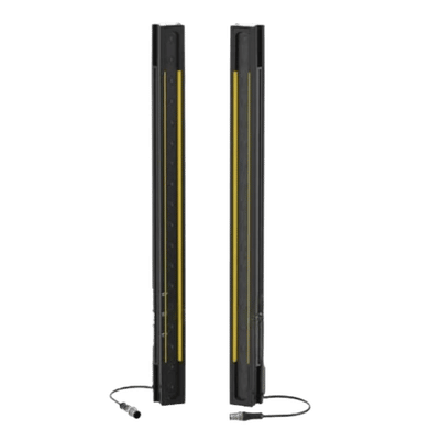
What Type 4 Adds Beyond Type 2
- Continuous, fail-safe self-testing — any internal malfunction triggers a safe fault state within a single response cycle
- Ultimate functional safety integrity – Cat.4 / PLe / SIL3 as defined in ISO 13849-1:2023 and IEC 61508
- Approved by risk assessment for consequences of death or permanent disability (per ANSI B11.0-2015 / ISO 12100)
- Synchronized with restart interlock – operator must reset from outside working zone
The QJKH ENT series protects fingers, hands, and bodies across three resolution classes spanning detection distance classes A through E (0–10 m up to 0–70 m). Every unit ships factory-direct with TÜV third-party test reports confirming compliance with IEC 61496-1,2:2020 — independently witnessed, never self-declared.
Our Safety Light Curtain Product Range
Different machine guarding scenarios need different light curtain configurations — a press point-of-operation does not have the same risk profile as a washdown line, an elevator door, or a palletizing conveyor. QJKH builds five product lines, each engineered for a specific class of application. Pick the line that matches your hazard, then follow the link for full specifications.
01
Flagship · High-risk
Explore the Type 4 ENT series →
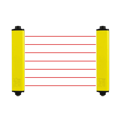
Type 4 Safety Light Curtain
For Cat.4 / PLe / SIL3 hazards — presses, robotic cells, hot-stamping
The ENT Type 4 series is the line of choice when a risk assessment demands the maximum ESPE classification under IEC 61496-1,2:2020. Continuous redundant self-monitoring captures any internal fault inside one response cycle, so single-point failures stay safe. Three resolution classes cover finger, hand, and body detection across distance ranges from 0.3 m up to 70 m.
Safety rating
Type 4 / PLe / SIL3
Resolution
14 / 25 / 45 mm
Detection range
Up to 70 m
Response time
From 6.0 ms

02
Lower-risk · Cost-optimized
Explore the Type 2 series →
Type 2 Safety Light Curtain
For PLc / SIL1 perimeter guarding — low-energy, recoverable hazards
Type 2 light curtains test themselves at fixed intervals rather than continuously, so they are appropriate where a risk assessment under ISO 13849-1 confirms a PLc / SIL1 ceiling: storage perimeters, access ways to slow-moving equipment, light-duty material handling. Choosing Type 2 where Type 2 is sufficient saves capital expenditure without bypassing compliance.
Safety rating
Type 2 / PLc / SIL1
Resolution
25 / 40 mm
Detection range
Up to 20 m
Best fit
Perimeter access
03
Material-flow zones
Explore muting configurations →
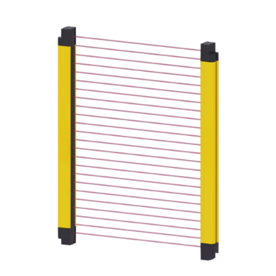
Muting Safety Light Curtain
For palletizing, conveyors, and AGV pass-through openings
A muting light curtain temporarily and selectively suspends the protective field so that pallets, totes, or product can pass — while keeping personnel safeguarding fully active. Two or four external muting sensors (T-shape or L-shape arrangements) confirm that the object signature matches a permitted load before muting fires, so an operator stepping into the gap re-arms protection instantly.
Safety rating
Type 4 + muting logic
Mute inputs
2 or 4 sensors
Resolution
25 / 40 mm
Best fit
Palletizers, conveyors
04
Passenger / freight elevator doors
Explore elevator light curtains →
Elevator Light Curtain
For passenger entrapment prevention and door re-open detection
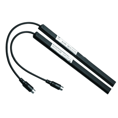
Elevator light curtains replace mechanical safety edges on passenger and freight elevator door systems. A dense beam matrix across the door opening detects passengers, luggage, and small objects within milliseconds, signaling the door operator to reverse and re-open before a closure event can occur. Slim profile and low-voltage design fit standard MRL door header retrofits.
Beam count
Typical 154 / 192
Detection height
Up to 1,800 mm
Supply
12–24 VDC
Best fit
MRL retrofit / OEM
05
Washdown / IP67 environments
Explore waterproof models →
Waterproof Safety Light Curtain
For food, beverage, pharma, marine, and outdoor packaging lines
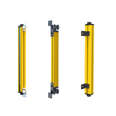
Standard IP65 housings rated for low-pressure water jets are not enough where high-pressure caustic washdown is part of the daily clean-in-place cycle. Our waterproof line steps the enclosure up to IP67, with stainless front lenses, sealed M12 connectors, and chemical-resistant cable jackets so the safety function survives detergent, brine spray, and pressure-wash protocols.
Enclosure
IP67 (IEC 60529)
Lens
Stainless / PMMA-IK08
Resolution
14 / 25 / 45 mm
Best fit
Food / pharma / marine
Not sure which line fits your machine? Send a short description of the application — hazard motion, body part at risk, plant environment, and incumbent safety controller — and our application engineering team will recommend a configuration with safety distance worked through under ISO 13855, typically within 48 hours. Cross-line accessories (cascading adapters, reflective columns, SRB safety relay modules, mounting brackets) are shared across the five product lines, so a multi-machine deployment can mix Type 4, Type 2, muting, and waterproof variants under one purchase order without sourcing duplicate consumables.
ENT Type 4 Series — Product Models and Shared Specifications (14 / 25 / 45 mm)
ISO 13855 requires three resolution classes for finger, hand, and body protection across ranges A-E, and each model uses the same safety architecture, IP65 enclosure, and optical synchronization parameters; only the beam pitch and the relevant target anatomy differs.
Finger Detection · 14 mm
ENT-14
- Beam pitch 10 mm
- Distance 0–10 m / 0–5 m near mode
- Min response 6.0 ms
For point-of-operation guarding on presses
Hand Detection · 25 mm
ENT-25
- Beam pitch 20 mm
- Distance 0–16 m
- Topology Cascading + reflective columns
For hydraulic press multi-side guarding
Body Detection · 45 mm
ENT-45
- Beam pitch 40 mm
- Distance 0–40 m / 0–70 m extended
- Logic Integral muting + dual freq A/B
For robotic cell entry + palletizing lines
ENT Series — Shared Specifications
| Parameter | ENT-14 | ENT-25 | ENT-45 |
|---|---|---|---|
| Optical axis spacing | 10 mm | 20 mm | 40 mm |
| Detection accuracy (resolution) | 14 mm | 25 mm | 45 mm |
| Detection distance classes | A: 0–10 m · B: 0–16 m · C: 0–5 m · D: 0–40 m · E: 0–70 m | ||
| Protection height | Up to 1,960 mm (configurable by beam count) | ||
| Response time | 6.0–30.8 ms (scales with beam count) | ||
| Safety rating | Type 4 · Cat.4 · PLe · SIL3 | ||
| Standards | IEC 61496-1,2:2020 · EN 61508-1~4:2020 · ISO 13849-1:2023 · GB 4584 | ||
| Enclosure rating | IP65 (IEC 60529) | ||
| Supply voltage | 24 VDC ±20% | ||
| Safety output (OSSD) | Dual PNP or NPN transistor (≤100 mA per channel) | ||
| Cross-section | 34 × 28 mm | ||
| Connection | M12 connector (standard, no proprietary cabling) | ||
| Configuration | Infrared one-button PNP/NPN switching (no DIP, no software) | ||
Cascading, Wiring, and Reflective Column Configuration
In multi-access applications with two or more entry openings, ENT models cascade through dedicated interfaces and share one core safety controller. Reflective corner columns redirect the protective field around bends — a single emitter/receiver pair can cover two or three boundaries of a danger zone without additional wiring.
Standard M12 connectors keep the bill of materials consistent and eliminate the proprietary cable lock-in carried by some Western brands.
Why M12 Standard Matters for Integrators
Mixing competing safety light curtain sensors into a legacy controller stack runs into the same recurring pain points across PLC integrator forums. Some Western brands ship proprietary snap-lock connectors over a standard M12 housing; others run OSSD self-diagnostic cycles whose timing conflicts with Allen-Bradley GuardLogix I/O modules, forcing the integrator into one-off engineering workarounds.
- Standard M12 housing on every ENT unit — no proprietary connector lock-in
- Dual PNP / NPN OSSD outputs, IR-switchable — drop-in compatibility with mainstream safety PLCs
- Configurable without software — no proprietary engineering tool required
ENT vs Competing Type 4 Safety Light Curtains — Specification Comparison
All Type 4 units on the market meet the same IEC 61496-2 baseline, so the real differentiators are detection range, response time, form factor, and integration hassle. Here’s a comparison of the QJKH ENT against 2 other competing safety light curtain lines with named specs – no high/medium/low rankings.
| Specification | QJKH ENT | Brand A (premium) | Brand B (mid) |
|---|---|---|---|
| Resolution options | 14 / 25 / 45 mm | 14 / 30 mm | 20 / 40 mm |
| Maximum detection distance | 70 m | 15 m | 20 m |
| Minimum response time | 6.0 ms | 6.5 ms | 12 ms |
| Cross-section profile | 34 × 28 mm | 41 × 27 mm | 30 × 30 mm |
| IP rating / connector | IP65 / Standard M12 | IP65 (proprietary + M12 adapter) | IP65 / Standard M12 |
| PNP / NPN switching | IR one-button | Software required | DIP switch |
| Beam status indicator | Per-segment LED | Full-length LED | Status LED only |
| Cascading + reflective column | Both supported | Cascading only | Cascading only |
| Pricing approach | Factory-direct, transparent factors | $$$$ premium tier | $$$ mid tier |
Why 70 m Matters for Palletizing and Conveyor Lines
At 70 m max detection range, the ENT-45 covers entire warehouse perimeter gates, palletizer line openings, and conveyor in-feed zones with one emitter-receiver pair. Equivalent coverage on competing lines typically requires multiple sender-receiver pairs daisy-chained through cascading adapters.
Every millisecond of response time translates to roughly 2 mm of additional safety distance at hand approach speed under ISO 13855. At 6.0 ms, an ENT-14 holds the protective field about 12 mm closer to the hazard than a 12 ms competing light curtain — preserving operator ergonomic reach without giving up safety integrity.
“We bench tested all 3 ENT configurations against our existing fleet of Banner LS and SICK deTec4 models before publishing this comparison. The 70 m E-class optics use higher-power IR emitters and frequency-coded synchronization, so we can sustain longer ranges without crosstalk on adjacent machines.”
Interested in a side-by-side spec comparison formatted around your plant and incumbent safety device brand?
Request a custom comparison sheetResolution Selection — 14 mm Finger / 25 mm Hand / 45 mm Body Detection Under ISO 13855
Resolution affects how closely a safety light curtain can be installed to the hazard zone. Finer resolution equates to shorter minimum safety distance, however the machine’s stopping performance must stop the hazardous movement short of the finger or hand reaching the danger point at the specified approach speed.
01
Risk assessment
Use ISO 12100 or ANSI B11.0-2015 to determine body part at risk and required safety integrity level (PL / SIL).
02
Map body part
14 mm for finger, 25-30 mm for hand, 45-70 mm for body / leg detection.
03
Calculate distance
Calculate safety distance with ISO 13855 – using the equation below.
04
Select model
Choose resolution + protection height + distance class to match your machine envelope.
ISO 13855 Safety Distance Formula
S = K × T + C
- S = minimum safety distance (mm)
- K = approach speed: 2,000 mm/sec for hand, 1,600 mm/sec for body
- T = total response time = light curtain response + machine stopping time (sec)
- C = penetration allowance = 8 × (d − 14) mm for d ≤ 40 mm; 850 mm for d > 40 mm (d = resolution)
Worked example — ENT-14 on a mechanical press:
Configuration: ENT-14 with 32 beams (d = 14 mm); response time t = 10.2 ms. Machine braking time = 100 ms.
S = 2,000 × (0.0102 + 0.100) + 8 × (14 − 14) = 220.4 mm
At 220 mm from the press opening, the ENT-14 achieves finger-level detection, yet keeps the operator well within ergonomic reach of the work station.
Decision Matrix — Application to Recommended Model
| Application | Recommended Model | Resolution | Distance Class | Mounting Note |
|---|---|---|---|---|
| Mechanical press point-of-operation | ENT-14 | 14 mm finger | A: 0–10 m | Perpendicular to access opening |
| Press brake operator zone (near distance) | ENT-14 | 14 mm finger | C: 0–5 m | Near-distance mode, <250 mm safety distance |
| Hydraulic press side guarding | ENT-25 | 25 mm hand | B: 0–16 m | Cascade + safety relay module (SRB-2A1B) |
| Robotic cell entry point | ENT-45 | 45 mm body | D: 0–40 m | Dual freq A/B against adjacent crosstalk |
| Palletizing line passage | ENT-45 + muting | 45 mm body | E: 0–70 m | Reflective column for U-shape coverage |
The on-site calculator ecosystem deployed on the Type 4 sub-pages automates every step of this procedure. Engineers can run the following tools directly through the web browser without registration:
Light Curtain Machine Guarding — Press, Robotic Cell, and Conveyor Applications
OSHA 1910.212(a)(3)(iv) lists power presses, shears, alligator shears, milling machines, jointers, power saws, and forming rolls as machines that “usually require point of operation guarding.” Each require a dedicated light curtain machine safeguarding configuration matched to the dominant hazard motion.
Mechanical Press Point-of-Operation Guarding
Stamping presses generate some of the highest pinch and shear hazards in metal fabrication. An ENT-14 mounts perpendicular to the press opening at the ISO 13855 calculated safety distance, providing a finger-resolution barrier across the point of operation. Any beam interruption during the cycle commands a safety stop within a 6.0–10.2 ms response window.
- Paired SRB-2A1B safety relay module for dual-channel OSSD monitoring
- Manual or automatic restart interlock per risk assessment outcome
- Compatible with mainstream safety controllers (Allen-Bradley GuardLogix, Siemens, Pilz)
Hydraulic Press Multi-Sided Protection
Hydraulic presses loaded from more than one side need multi-side machine guarding. An ENT-25 cascade handles this directly — two or three units interconnect through cascading adapters and feed a single safety controller. Reflective corner columns redirect the protective field around bends where direct mounting is impossible.
Robotic Cell Entry Points
Robotic cells need body detection at perimeter entry points combined with muting for automated material handling. The ENT-45 supports muting so pallets and fixtures pass through the protective field without interrupting the cycle, while maintaining full personnel safeguarding. For dedicated palletizing and AGV pass-through openings, see our purpose-built muting safety light curtain configurations with two- and four-sensor T- and L-shape arrangements.
Why Dual Frequency A/B Channels Matter
A recurring reliability complaint in industrial maintenance forums describes safety light curtains tripping mid-cycle on tire-building and packaging lines — almost always traced back to optical crosstalk between adjacent light curtain sensors mounted in close proximity.
- ENT units transmit on dual frequency bands (A and B) selectable in firmware
- Adjacent machines on opposite frequencies cannot trigger one another
- Per-beam indicator lights display which beam is blocked or misaligned for trouble-free diagnosis
Press Brake Bending Machine
Press brakes are typically guarded as close to the operator as ergonomics allow, to preserve reach. In near-distance mode (Class C: 0–5 m), the ENT-14 with its 6.0 ms response time holds the safety distance below 250 mm — productive operation without breaking ISO 13855 compliance.
Conveyor and Palletizing Line Passage
Conveyor lines and automated palletizing zones use the ENT-45 with integrated muting to allow pallets and product through the protective field while maintaining personnel safeguarding. The 70 m E-class detection distance covers the full warehouse perimeter gates and long conveyor passes with a single sender-receiver. Detailed muting logic and sensor placement for T- and L-shape arrangements are documented on the muting safety light curtain page.
Washdown, Food, and Pharma Lines
Standard IP65 housings cope with low-pressure splash but degrade under high-pressure caustic clean-in-place protocols common in dairy, beverage, meat processing, and pharmaceutical packaging. Where the duty cycle includes daily detergent or chemical washdown, an upgraded enclosure is required — see the waterproof safety light curtain line with IP67 sealing, stainless front lenses, and chemical-resistant cable jackets engineered to survive the wash cycle.
Elevator and Door-Reopen Applications
Passenger and freight elevator doors require a denser beam matrix and lower supply voltage than industrial machine guarding curtains. A dedicated elevator light curtain handles entrapment prevention and door re-open detection with up to 192 closely spaced beams across the door opening — the same optical safety principle, tuned for a different installation envelope.
Working on a specific application? Send us your machine drawings – our application engineers will design a configuration within 48 hours
Customer Results and Machine Guarding Return on Investment
Machine safeguarding is a category most operations leaders underestimate — the upfront capital cost looks small, while the return on a single prevented incident dwarfs the investment. Industry studies put that multiple in the 3× to 6× range over a multi-year horizon.
Machine Safeguarding ROI — Industry Data
1:3
Liberty Mutual exec poll — $1 spent on safety saves $3
1:6
OSHA-estimated ratio of saved dollars per safety dollar
$95,204
Average amputation claim cost (NCCI 2013–2015)
$1.51B
Global safety light curtain market 2026 (FBI report)
Industry studies show machine safeguarding investments produce positive ROI within 12-24 months in most fabrication and manufacturing operations. Precise payback depends on application, throughput, and incumbent insurance experience modifier.
The Real Cost of an Unguarded Press
An ISHN analysis following the OSHA Safety Pays estimator showed that concretely. One shop that fabricates metal and did not use guarding on a press brake cost caused a claim of amputation, $88,991 direct cost and $97,890 indirect cost totaling $186,881. One installed an illumination curtain, e-stop, and perimeter guarding on the same machine.
$8,500
Typical machine guarding investment per press
$186,881
Single amputation claim total cost (OSHA Safety Pays)
22×
Cost Ratio of one avoided incident vs guarding capex
Application Case Patterns
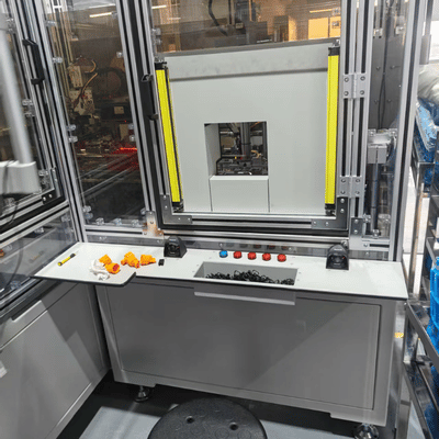
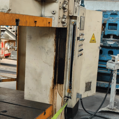
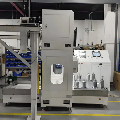
The value of the ENT across mechanical press, robotic cell and palletizing applications is enhanced in three ways: 1. avoiding injury cost (Liberty Mutual / NSC data above), 2. production downtime avoided (relative to mechanically hard guarding), 3. lowered OSHA citation exposure. Machine guarding has been consistently ranked in OSHA’s top 10 most-cited violations since 2016.
Building an internal business case for safety capex?
Request Customized ROI Analysis →
×
![Expanded View]()
Manufacturing Excellence
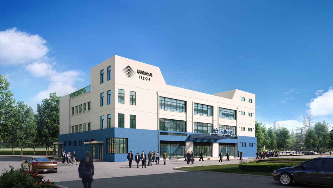
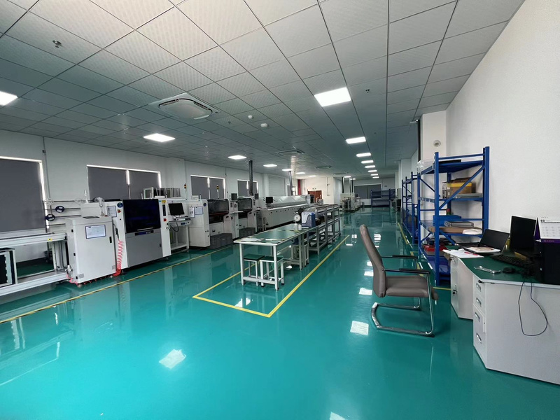
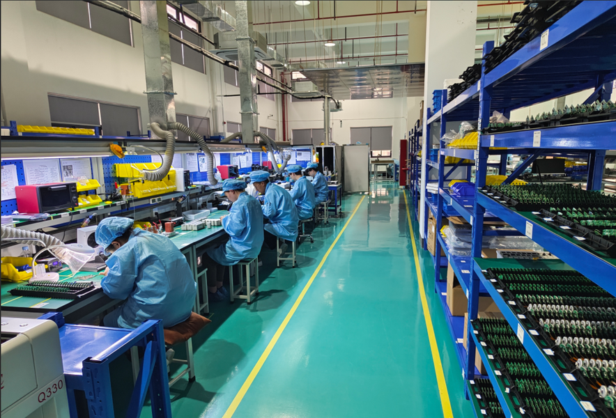
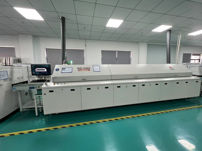
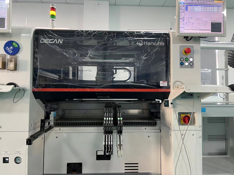
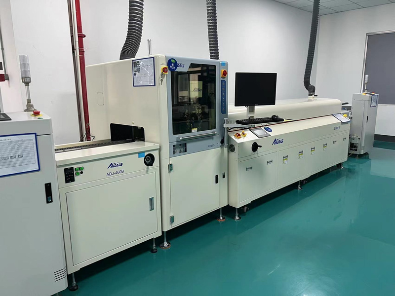
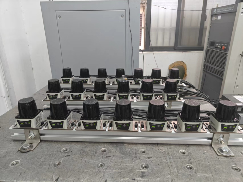
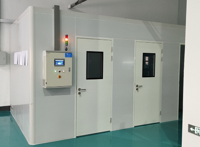
Advanced production facilities ensuring top-tier reliability for our Safety Light Curtains.
×
![Expanded View]()
Certifications and Compliance — IEC 61496 / ISO 13849 / TÜV / IEC 61508
Every ENT series unit ships with a TÜV third-party test report — independent verification that the device meets international safety standards. These reports are not self-declarations; they are available on demand for procurement audits and customer compliance reviews.
Type 4
IEC 61496-1,2:2020
Cat.4 / PLe
ISO 13849-1:2023
SIL3
IEC 61508-1~4:2020
IP65
IEC 60529
CE
European Conformity
TÜV
Independent test reports
GB 4584
China national standard
EN 61326-1
EMC compliance
What Each Standard Means in Practice
Type 4 (IEC 61496-1,2:2020)
highest ESPE class — continuous redundant self-monitoring, automatic cross-checking, and single-fault tolerance.
PLe (ISO 13849-1:2023)
highest performance level for safety-related control systems, with mean time to dangerous failure (MTTFd) exceeding 100 years per channel.
SIL3 (IEC 61508)
probability of dangerous failure per hour (PFHd) between 10⁻⁸ and 10⁻⁷ — the highest integrity level realistically achievable for general-purpose safety light curtains.
IP65 (IEC 60529)
dust-tight, protected against low-pressure water jets from any direction — appropriate for typical factory environments.
Manufacturing and Testing Transparency
The ENT series is manufactured in our 5,000 m² electronics facility inside the Hangzhou Airport Economic Demonstration Zone, equipped with high-precision SMT placement lines and 3D AOI inspection. An adjacent 1,000 m² R&D laboratory runs EMC, thermal cycling, humidity, vibration, shock, and IP ingress testing — every test on-site, which is what makes rapid certification of new product variants possible.
We built our own EMC and IP test capability because relying on external labs added 8 to 12 weeks to every new variant qualification. Today we run TÜV witness tests inside our own laboratory — cutting that interval to 2–3 weeks and giving procurement customers full traceability across all test parameters.— QJKH R&D Laboratory, ENT certification program lead
Procurement Guide — Pricing Factors, Lead Time, OEM, and Free Sample Program
Western brand safety light curtains are typically quoted off opaque deal sheets, with a 30–50% distributor markup baked into the end-user sell-through price. As a factory-direct manufacturer, QJKH publishes the cost drivers up front, so procurement teams can model their own bill of materials before requesting a formal quote.
Resolution Class
14 mm finger units carry a premium over 45 mm body units due to higher beam density and tighter optical tolerances per linear meter of protection height.
Protection Height
For a given resolution, taller curtains require more optical cell pairs — component cost scales roughly linearly with protection height up to the 1,960 mm maximum.
Detection Distance Class
Standard A/B/C optics differ from D and E long-range variants. E-class units use higher-power IR emitters and frequency-coded synchronization for the 70 m capability.
Order Volume
Volume-tiered pricing applies to multi-unit and repeat orders. OEM contracts qualify for additional preferential pricing structures.
Accessories and Configuration
Cascading adapters, reflective columns, safety relay modules (SRB-2A1B), mounting brackets, and custom cable lengths priced separately from the core curtain.
OEM and Customization
Custom protection heights, extended cable lengths, application-specific firmware, and OEM branding are all available. TÜV witness testing of custom variants is performed in our own laboratory.
Core OEM Capabilities:
- Private Label & Branding
- Application-Specific Firmware
- On-Site TÜV Witness Testing
- Custom Cable Configurations
Free Sample Program for Qualified Buyers
QJKH operates one of the lowest-friction evaluation programs in the industrial safety sensor market: free ENT test units shipped to qualified buyers for hands-on integration trials. Verifying optical alignment, response time, IP65 sealing, and build quality on a live machine is the most efficient way to validate the platform before committing to a volume purchase. Speak to our application engineering team to qualify and arrange delivery.
Request a Free Sample for evaluationEngineering Tools & Resources
Streamline your safety planning and procurement process. Use our interactive calculators and decision frameworks to model return on investment and select the exact compliance level your machinery requires under ISO and OSHA standards.
CALC
Financial Model
Machine Guarding ROI Calculator
Quantify the financial impact of machine safeguarding. Compare the upfront capital expenditure of ENT light curtains against industry-average incident costs to build a robust internal business case for your safety upgrades.
Launch Calculator →
TREE
Compliance Guide
Type 2 vs Type 4 Decision Tree
Navigate ISO 13849 requirements step-by-step. Map your specific hazard profile, severity of potential injury, and access frequency to determine definitively whether a Type 2 or Type 4 safety architecture is legally mandated.
Open Decision Tree →
FAQ
Safety Light Curtain — Frequently Asked Questions
Expert answers on safety distance calculations, resolution selection, integration, and compliance for industrial machine guarding.
What is the difference between Type 2 and Type 4 safety light curtains?
Type 2 devices run periodic self-tests at fixed intervals — a fault that appears between tests can go undetected until the next cycle. Type 4 units run continuous redundant self-diagnosis with automatic cross-checking, so any internal fault is captured within a single response cycle. For high-hazard applications (mechanical presses, hydraulic presses, robotic cells, milling machines under OSHA 1910.212), Type 4 is the minimum requirement under an ISO 13849 risk assessment.
How do I calculate the safety distance for installation under ISO 13855?
Use the formula S = K × T + C, where K is the approach speed (2,000 mm/s for hands, 1,600 mm/s for full body), T is the total system response time (light curtain + machine stopping time), and C is the penetration allowance based on resolution. Our on-site interactive calculator runs every variable for ENT models with a single click.
How do I choose between 14 mm, 25 mm, and 45 mm resolution?
Selection follows the body part at risk identified in your risk assessment. 14 mm gives finger-level detection — required at point-of-operation zones on presses where the operator’s hands enter the hazardous area. 25 mm covers hand detection where operators reach into the machine for basic perimeter guarding. 45 mm provides body detection at perimeter gates, robotic cell entries, and palletizing line passages.
Are your safety light curtains independently certified?
Yes. Every ENT series unit is certified to IEC 61496-1,2:2020 under third-party TÜV witnessing, with full test reports on file and available on demand for procurement audit. Our Hangzhou laboratory performs EMC, thermal cycling, vibration, shock, and water ingress testing in-house. This is third-party verified accreditation — not self-assertion.
What is light curtain muting and blanking, and what is fixed vs floating blanking?
Muting temporarily suspends the entire protective field during an automated cycle — letting pallets or workpieces pass through — and re-arms the safety function as soon as the muting sensors confirm the object has cleared. Blanking permanently masks specific beams to accommodate fixed obstacles (fixtures, brackets) inside the protective field. Both are configured on ENT units without any software tool.
Will your light curtains integrate with existing Allen-Bradley GuardLogix or Siemens safety controllers?
Yes. Every ENT unit ships with dual-channel OSSD outputs (PNP or NPN, IR-switchable) on a standard M12 connector, so it lands directly on Allen-Bradley GuardLogix, Siemens, Pilz, and other mainstream safety PLC platforms without proprietary cabling or vendor-locked engineering software. Cascading and reflective-column accessories share the same connector convention across the ENT range.
Can I get a free sample to test before ordering?
Yes. Qualified buyers receive a free ENT series sample for hands-on evaluation — verify optical alignment, response time, IP65 sealing, and build quality on a real machine before committing to a volume order. Contact our application engineering team to apply and arrange shipment.
Do you support OEM labeling and customization?
Yes. We support custom protection heights, extended cable lengths, application-specific firmware, and OEM labeling. Custom variants undergo TÜV witness testing in our in-house lab — typically within 2–3 weeks, versus 8–12 weeks at an external facility.
Trending now