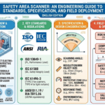
Functional Safety Standards: IEC 61508, ISO 13849 & IEC 62061

Engineering Guide · Machinery Functional Safety

Functional Safety Standards for Machinery: ISO 13849, IEC 62061 & IEC 61508

A practical guide to the functional safety standards used in industrial machinery — how risk assessment leads to safety functions, how ISO 13849 and IEC 62061 evaluate safety-related control systems, and where IEC 61508 fits into the wider functional-safety framework.

Updated: September 2026
Topic: Functional Safety
Focus: Industrial Machinery
Level: Engineering / Integration
In Brief

Functional safety is the part of machine safety that depends on a control system responding correctly when a defined safety-related condition occurs. For industrial machinery, the process normally begins with risk assessment and risk reduction, followed by definition of the required safety functions and selection of an appropriate safety-related control-system methodology.

Machinery safety standards are often presented as a list of numbers: ISO 12100, ISO 13849, IEC 62061, IEC 61508, IEC 61496 and many more. The harder question is understanding what role each standard actually plays.

ISO 12100 provides the general machinery risk-assessment and risk-reduction methodology. Once a safety-related control function is required, standards such as ISO 13849-1 and IEC 62061 provide methods for designing and evaluating the safety-related control system.

IEC 61508 has a broader role. It is a generic functional-safety standard for electrical, electronic and programmable electronic safety-related systems. It provides important concepts used throughout functional safety, but machinery projects should not automatically treat it as a replacement for machinery-specific standards.

This distinction matters because a component marked with a high PL, SIL or Category capability does not automatically give the complete machine the same safety performance. Functional safety is evaluated at the level of the complete safety function, including the input subsystem, logic, output subsystem, diagnostics, architecture and validation.

What You Will Learn

How the Main Machinery Safety Standards Fit Together

  • Why ISO 12100 is the starting point for machinery risk assessment rather than a PL or SIL calculation standard.
  • What IEC 61508 covers and how its role differs from machinery-specific functional-safety standards.
  • How ISO 13849-1 uses safety functions, Category, required Performance Level and achieved Performance Level.
  • How IEC 62061 approaches machinery functional safety using Safety Integrity Level concepts.
  • Why PL and SIL should not be treated as simple interchangeable marketing labels.
  • How component safety ratings differ from the achieved performance of the complete machine safety function.
  • Where standards for safety light curtains, laser scanners, safeguard positioning and machine electrical equipment fit into the wider standards structure.
  • How the EU Machinery Regulation fits into the legal and standards context for machinery placed on the European market.
Scope: this guide focuses on functional safety for industrial machinery. It is intended as an engineering overview and does not replace the applicable standards, machine-specific Type-C standards, risk assessment or formal validation for a particular machine.
02 · Standards Framework

How Machinery Safety Standards Fit Together

Machinery functional safety is easier to understand when the standards are viewed as parts of an engineering process rather than as competing rulebooks.

A machinery safety project normally begins by identifying hazards and reducing risk. If part of that risk reduction depends on a control system — for example, stopping hazardous motion when a guard opens or a safety light curtain is interrupted — then a safety-related control function must be defined.

Standards such as ISO 13849-1 and IEC 62061 then provide methodologies for designing and evaluating the safety-related control system. Other standards may define the characteristics of the protective device, its positioning, machine electrical requirements or requirements for a particular type of machine.

The result is not one standard replacing all the others. Instead, several standards may apply to different layers of the same machine safety function.

A Practical Engineering Flow

01
Risk Assessment
Identify hazards, estimate and evaluate risk, and determine what risk reduction is required. ISO 12100 provides the general machinery methodology for this stage.
02
Define the Safety Function
Specify what must happen when a safety-related condition occurs: detect access, stop motion, prevent restart, inhibit movement or perform another defined risk-reduction function.
03
Determine Required Performance
Define the required performance of the safety-related control function using the selected machinery methodology, such as PLr under ISO 13849-1 or the required SIL under IEC 62061.
04
Design the Control Architecture
Select the input subsystem, safety logic and output subsystem, then evaluate architecture, diagnostics, reliability and fault behavior according to the chosen control-system standard.
05
Apply Device-Specific Requirements
Protective equipment such as safety light curtains and safety laser scanners may be subject to additional product or application standards covering detection capability, response behavior and installation.
06
Position the Safeguard
Where electro-sensitive protective equipment is used, safeguard positioning and safety distance must account for approach speed, system response time and machine stopping performance.
07
Validate the Safety Function
Confirm that the implemented safety function behaves as specified and achieves the required performance. Validation includes more than checking individual component ratings.
Core Principle

Standards should follow the safety function, not the product label. A machine builder first defines the hazard and required risk reduction, then determines which control-system, protective-device, positioning and machine-specific standards apply.

What Role Does Each Main Standard Play?

Standard Main Role Typical Question It Helps Answer
ISO 12100 General machinery risk assessment and risk reduction. What are the hazards, and what risk-reduction measures are required?
ISO 13849-1 Design and evaluation of safety-related parts of machine control systems using Category and Performance Level concepts. What performance is required, and does the implemented safety-related control function achieve it?
ISO 13849-2 Validation of safety-related parts of control systems. Has the safety function been correctly implemented and validated by analysis and testing?
IEC 62061 Functional safety of safety-related control systems for machinery using SIL-based methodology. How should the safety-related control system be designed and evaluated using the machinery SIL framework?
IEC 61508 Generic functional-safety framework for electrical, electronic and programmable electronic safety-related systems. What broader lifecycle and functional-safety principles apply to E/E/PE safety-related systems?
IEC 61496 Series Product requirements for electro-sensitive protective equipment. What requirements apply to protective devices such as safety light curtains and related electro-sensitive equipment?
ISO 13855 Positioning of safeguards with respect to human approach. How far should a protective device be positioned from the hazard based on response and stopping behavior?
IEC 60204-1 General requirements for electrical equipment of machines. How does the safety-related function fit into the wider machine electrical system?

Type-A, Type-B and Type-C Machinery Standards

Type-A Standards — Basic Safety Concepts

These provide basic concepts, principles for design and general aspects that can be applied broadly across machinery. ISO 12100 is a key example.

Type-B Standards — Generic Safety Aspects or Safeguards

These address particular safety aspects or types of safeguards that can be used across many machine categories. Control-system safety, safeguard positioning and electro-sensitive protective equipment fall into this broader layer.

Type-C Standards — Specific Machine Categories

These contain detailed requirements for a particular machine or group of machines. Where an applicable Type-C standard exists, it can define requirements more specifically than the general Type-A or Type-B guidance.

This hierarchy is important because a machine-specific standard can change the practical design requirements for a particular application. A general statement such as “this device is Type 4, therefore it is suitable for every machine” is not sufficient.

The actual machine standard, risk assessment and complete safety function still determine whether the selected safeguard and control architecture are appropriate.

Engineering note: standards interact at different levels. Risk assessment, safety-function design, protective-device selection, safeguard positioning, electrical integration and validation should be treated as connected engineering activities rather than isolated compliance checks.
03 · Generic Functional Safety Framework

IEC 61508: The Broader Functional Safety Framework

IEC 61508 provides a generic functional-safety framework for electrical, electronic and programmable electronic safety-related systems. Its importance extends across many industries, but machinery projects often use more application-specific standards for the actual machine control system.

IEC 61508 addresses systems in which electrical, electronic or programmable electronic technology performs a safety function. A central concept is that functional safety should be managed systematically throughout the lifecycle of the safety-related system.

The standard provides a broad framework covering topics such as safety requirements, hardware integrity, systematic capability, software, validation, operation, maintenance and modification.

One of IEC 61508’s important purposes is to support the development of standards for particular products and application sectors. It can also provide a framework where a suitable sector-specific standard does not exist.

Important Distinction

IEC 61508 is broader than machinery safety. For a typical industrial machine, the relevant machinery-specific control-system standard may be ISO 13849-1 or IEC 62061. IEC 61508 should therefore not automatically be substituted for those standards simply because it is a widely recognized functional-safety framework.

The Safety Lifecycle Concept

One of the most influential ideas in IEC 61508 is the safety lifecycle. Functional safety is not treated as something that can be demonstrated only by testing a finished product. It must be considered from hazard analysis and safety requirements through design, implementation, validation, operation and later modification.

01
Hazard & Risk Analysis
Understand the hazardous conditions and determine what safety functions are required to reduce risk.
02
Safety Requirements
Define what each safety function must do and the required integrity associated with that function.
03
Design & Implementation
Develop the hardware and software architecture using methods appropriate to the required safety integrity.
04
Integration & Validation
Verify that the implemented system performs the specified safety functions and satisfies the defined safety requirements.
05
Operation & Maintenance
Functional safety must continue to be maintained after commissioning, including procedures for operation, testing and maintenance.
06
Modification
Changes to a safety-related system may affect assumptions, diagnostics or performance and therefore require controlled review and revalidation.

IEC 61508 Is a Multi-Part Standard

IEC 61508 is not a single document. The current second edition is published as a seven-part series, with different parts addressing general requirements, hardware, software, terminology and supporting guidance.

Part Primary Role
IEC 61508-1 General requirements and the overall framework for functional safety of E/E/PE safety-related systems.
IEC 61508-2 Requirements for electrical, electronic and programmable electronic safety-related systems, particularly hardware-related design and integrity.
IEC 61508-3 Software requirements for software that forms part of, or is used in the development of, the safety-related system.
IEC 61508-4 Definitions and abbreviations used throughout the IEC 61508 series.
IEC 61508-5 Examples of methods for determining safety integrity levels.
IEC 61508-6 Guidance on applying the hardware and software requirements in Parts 2 and 3.
IEC 61508-7 Overview of techniques and measures relevant to functional safety engineering.

Safety Integrity Levels in IEC 61508

IEC 61508 uses Safety Integrity Levels to express levels of safety integrity for safety functions. Within the generic IEC 61508 framework there are four levels: SIL 1 through SIL 4, with SIL 4 representing the highest safety integrity level.

This is one reason machinery engineers should be careful when comparing standards. The machinery-specific IEC 62061 framework does not simply reproduce every aspect of IEC 61508, and the SIL terminology used in one context should not be transferred mechanically into another.

Safety Integrity

SIL 1

Lowest of the four IEC 61508 safety integrity levels.

Safety Integrity

SIL 2

Higher integrity requirements than SIL 1.

Safety Integrity

SIL 3

High safety integrity within the generic IEC 61508 framework.

Safety Integrity

SIL 4

Highest safety integrity level defined by IEC 61508.

Why Machinery Engineers Usually Work With ISO 13849 or IEC 62061

Industrial machinery has its own established functional-safety methodologies. ISO 13849-1 provides the Performance Level approach for safety-related parts of machine control systems, while IEC 62061 provides a machinery-specific SIL-based methodology.

IEC 61508 remains important for understanding the broader functional safety framework and may also be highly relevant to the design or assessment of components and subsystems. But the applicable machinery standard and machine-specific requirements should guide the final machine safety architecture.

Common IEC 61508 Misunderstandings

“IEC 61508 is the mandatory parent standard for every machine.”

Too broad. IEC 61508 provides a generic functional-safety framework, while machinery projects commonly apply machinery-specific standards such as ISO 13849-1 or IEC 62061.

“If a component is SIL 3, the machine safety function is SIL 3.”

No. Component capability is only one element of the complete safety function. Architecture, diagnostics, reliability, integration and validation still matter.

“SIL is simply a product quality grade.”

SIL relates to the safety integrity required or achieved for a safety function within the applicable functional-safety framework. It should not be treated as a general quality ranking.

“The highest SIL should always be selected.”

Functional-safety targets are determined from the required risk reduction and applicable methodology. Higher numbers are not a substitute for correct risk assessment and safety-function design.

Engineering note: IEC 61508 provides foundational concepts for functional safety, including safety lifecycle management and safety integrity. For machinery, those concepts should be applied in the context of the appropriate machinery-specific standards rather than reduced to a simple hierarchy of “parent” and “child” standards.
04 · Performance Level Method

ISO 13849-1:2023 — Category, PL and PLr Explained

ISO 13849-1 provides a methodology for designing and evaluating safety-related parts of machine control systems. Its Performance Level approach combines architecture, component reliability, diagnostic capability and resistance to common-cause failures.

A common mistake is to begin with a component label such as PL e or Category 4. In practice, the process begins earlier: the machine risk assessment identifies a required safety function and the level of risk reduction that function must provide.

ISO 13849-1 then provides a method for designing the safety-related parts of the control system that perform that function and for evaluating the achieved Performance Level.

The standard applies to safety-related control systems using different technologies and forms of energy, including electrical, hydraulic, pneumatic and mechanical technologies. It is therefore broader than a standard for safety PLCs or electronic devices alone.

From PLr to Achieved PL

01
Define the Safety Function
Specify the triggering condition, required machine response, safe state, relevant operating modes and other characteristics of the safety function.
02
Determine PLr
Establish the required Performance Level (PLr) from the risk assessment and applicable machine requirements. A machine-specific Type-C standard may also specify or influence the required performance.
03
Define the SRP/CS
Identify the safety-related control-system elements that perform the function, typically including the input, logic and output subsystems.
04
Evaluate the Architecture
Determine the relevant Category and evaluate the architecture’s resistance to faults and its behavior when faults occur.
05
Evaluate Reliability & Diagnostics
Consider parameters such as MTTFd, DCavg and measures against common-cause failures (CCF), together with systematic safety measures.
06
Determine Achieved PL
Evaluate the achieved Performance Level of the relevant subsystems and complete safety-related control function using the applicable ISO 13849 methodology.
07
Compare PL With PLr
Confirm that the achieved performance is sufficient for the required safety function and then validate the implemented function.
Key Distinction

PLr is the required target; PL is the achieved performance. A component can have safety data suitable for a high-performance architecture, but that does not by itself establish the PL of the complete machine safety function.

Performance Levels: PL a to PL e

ISO 13849 uses five Performance Levels: PL a, b, c, d and e. PL a represents the lowest safety-related performance within this scale and PL e the highest.

These levels should not be interpreted as simple product grades. Performance Level describes the ability of the safety-related parts of the control system to perform the specified safety function under foreseeable conditions.

Performance Level

PL a

Lowest level within the ISO 13849 PL scale.

Performance Level

PL b

Higher safety-related performance than PL a.

Performance Level

PL c

Intermediate safety-related performance.

Performance Level

PL d

High safety-related performance.

Performance Level

PL e

Highest level within the ISO 13849 PL scale.

What Are Categories B, 1, 2, 3 and 4?

Category describes important structural and fault-response characteristics of the safety-related control architecture. It is one input to the Performance Level evaluation — not the final Performance Level itself.

Category General Architectural Idea Fault / Diagnostic Principle
B Basic safety-related design principles and suitable components are applied. The occurrence of a fault can lead to loss of the safety function.
1 Builds on the basic principles and places greater emphasis on well-tried components and well-tried safety principles. Improved reliability reduces the likelihood of failure, but a fault can still result in loss of the safety function.
2 Adds testing or monitoring of the safety function at suitable intervals. Certain faults can be detected by the test function, although a dangerous failure can exist between tests.
3 Uses an architecture intended to maintain the safety function in the presence of a single fault. Some faults are detected, but not every possible fault must be detected. Accumulated undetected faults can still matter.
4 Uses a highly fault-tolerant architecture with strong diagnostic requirements. Single faults should not cause loss of the safety function, and fault detection and fault accumulation are addressed more stringently than in lower categories.
Important

Category 4 does not automatically equal PL e. Category describes architecture and fault behavior. The achieved Performance Level also depends on reliability, diagnostic coverage, common-cause failure measures and other safety-related design requirements.

The Main Parameters Behind the Achieved PL

Category
Describes important structural characteristics of the safety-related subsystem and how it behaves when faults occur.
MTTFd
Mean Time To Dangerous Failure is a reliability parameter used in evaluating the dangerous-failure behavior of components or channels within the applicable ISO 13849 methodology. It should not be interpreted as the actual expected service life of the complete machine.
DC / DCavg
Diagnostic Coverage represents the effectiveness of diagnostics in detecting dangerous failures. DCavg is used at the subsystem level when evaluating the average diagnostic coverage of the relevant architecture.
CCF
Common Cause Failure measures address failures that can affect multiple channels from a common cause. Redundancy is less effective if the same event can defeat both channels.
Systematic Measures
Design procedures, software measures, specification discipline, environmental considerations and other methods are also used to reduce systematic failures.
Validation
The final safety function must be validated against its safety requirements. Calculation alone is not the end of the functional safety process.

Think in Complete Safety Functions

Input

Detect the Safety Condition

Examples include interlocks, emergency-stop devices, safety light curtains and safety laser scanners.

Logic

Evaluate the Safety Signals

Safety relays, configurable safety controllers or safety PLCs may perform this part of the function.

Output

Achieve the Safe State

Contactors, drive safety functions or other final control elements perform the required machine response.

The achieved Performance Level must therefore be considered across the relevant safety-function architecture rather than assigned solely from the highest-rated component in the chain.

Common ISO 13849 Misunderstandings

“Category 4 automatically means PL e.”

No. Category is an architectural parameter. The achieved PL depends on additional reliability, diagnostic and common-cause failure considerations.

“A PL e component makes the whole machine PL e.”

No. Component capability is only part of the complete safety function. Input, logic, output, integration and validation all need to support the required performance.

“PLr is printed on the safety component datasheet.”

PLr is a required target for the safety function. It comes from the machine risk assessment and applicable requirements, not from the rating of one selected component.

“MTTFd tells me how long the machine will run before failure.”

No. MTTFd is a statistical reliability parameter used in functional safety evaluation. It is not a prediction of the actual service life of a particular machine.

“Two channels automatically create a Category 3 or Category 4 system.”

No. Channel count alone does not establish Category. Architecture, fault behavior, diagnostics, reliability and common-cause failure measures must also satisfy the relevant requirements.

2026 Standards Update

ISO/TR 13849-3:2026 Adds a Markov-Based PFH Calculation Method

In 2026, ISO published ISO/TR 13849-3:2026. The technical report provides Markov-model-based formulas for estimating PFH for selected single-channel and two-channel architectures.

It is intended as an alternative calculation approach to the simplified quantitative procedure in ISO 13849-1. It does not replace ISO 13849-1 or change the basic requirement to define, design and validate the complete safety function.

Engineering note: ISO 13849-1 is a methodology for designing and evaluating safety-related control systems. The correct engineering question is not “Which component has the highest PL?” but “Does the complete implemented safety function achieve or exceed the required PLr and has that result been validated?”
05 · SIL Method for Machinery

IEC 62061 — SIL for Machinery Safety-Control Systems

IEC 62061 provides a machinery-specific functional-safety methodology for the design, integration and validation of safety-related control systems. It uses Safety Integrity Level concepts to evaluate the safety functions performed by the machine control system.

IEC 62061 is a sector-specific machinery standard within the broader IEC 61508 functional-safety framework. It focuses on safety-related control systems for machines rather than on all forms of functional safety across every industry.

The standard can be applied to control technologies used individually or in combination to perform safety functions. The 2021 edition expanded the framework beyond electrical technologies and updated the design process, subsystem evaluation, software requirements, configuration management and validation requirements.

As with ISO 13849, the starting point is not the SIL printed on one component. The process begins with the required machine safety function and the level of safety integrity that function must achieve.

A Practical IEC 62061 Design Process

01
Define the Safety Function
Specify what condition triggers the function, what safe response is required, the relevant operating modes, response time and other functional requirements.
02
Determine the Required SIL
Determine the level of safety integrity required for the function from the machine risk assessment and applicable machine-specific requirements.
03
Design the SCS
Design the safety-related control system (SCS) used to perform the safety function, including the necessary input, logic and output subsystems.
04
Evaluate the Subsystems
Evaluate reliability, architecture, diagnostic behavior, common-cause failures and the maximum SIL that can be claimed for the relevant subsystems.
05
Calculate the Safety Function PFH
Combine the relevant dangerous-failure contributions of the subsystems to evaluate the probability of dangerous failure per hour for the complete safety function.
06
Check Systematic Integrity
Confirm that systematic design measures, software, parameterization, configuration management and other lifecycle requirements are appropriate for the required safety integrity.
07
Verify & Validate
Verify the design and validate that the implemented safety-related control system performs the required safety function with the specified integrity.
Key Principle

SIL belongs to the safety function, not simply to one component. A safety device or controller may have a stated SIL capability or maximum SIL, but the complete implemented safety function still needs to satisfy the required integrity, architecture, reliability and validation requirements.

SIL 1, SIL 2 and SIL 3 in Machinery

For machinery functional safety under IEC 62061, safety functions are evaluated within the range SIL 1 to SIL 3. Higher SIL represents a higher level of safety integrity and therefore a lower acceptable probability of dangerous failure for the safety function.

This should not be confused with the generic IEC 61508 framework, which also defines SIL 4. IEC 62061 is a machinery-sector standard and its machinery methodology is focused on SIL 1 through SIL 3.

Machinery Safety Integrity

SIL 1

Lowest of the three Safety Integrity Levels used for machinery safety functions under IEC 62061.

Machinery Safety Integrity

SIL 2

Represents a higher required or achieved safety integrity than SIL 1.

Machinery Safety Integrity

SIL 3

Highest Safety Integrity Level used within the IEC 62061 machinery framework.

PFH: Probability of Dangerous Failure per Hour

IEC 62061 evaluates random hardware safety integrity using the probability of dangerous failure per hour (PFH) for safety-related control functions operating in the relevant high-demand or continuous-demand context.

PFH is not simply the failure rate of one safety relay, sensor or controller. The dangerous-failure contributions of the relevant subsystems are considered as part of the complete safety function.

This is why selecting individual components with high SIL capability does not remove the need for system-level reliability calculation and validation.

Think in Subsystems

Input Subsystem

Detect the Safety Condition

Examples include emergency-stop devices, interlocks, safety light curtains, safety laser scanners and other safety-related inputs.

Logic Subsystem

Evaluate and Process

Safety relays, configurable safety controllers or safety PLCs can provide the logic necessary to perform the safety function.

Output Subsystem

Achieve the Safe State

Contactors, drive safety functions and other final control elements execute the required machine response.

The complete safety function may therefore contain several subsystems, each with its own reliability data, architecture and maximum achievable SIL.

The overall function cannot simply claim the highest rating of the strongest subsystem. The weakest applicable constraint can limit the integrity that can be claimed for the complete function.

What Determines the Achieved SIL?

PFH
The calculated probability of dangerous failure per hour of the complete safety-related control function.
Architecture
The subsystem structure and fault tolerance influence how dangerous failures affect the safety function.
Diagnostics
Diagnostic measures can detect dangerous failures and therefore affect the reliability and maximum SIL that can be claimed.
Common Cause Failures
Redundant paths can still be compromised by failures that affect multiple channels from a common cause, so CCF measures remain important.
Maximum SIL
A subsystem has architectural and systematic constraints that can limit the maximum SIL that may be claimed, even if its PFH value appears numerically low.
Systematic Safety Integrity
Specification, design processes, software, parameterization, configuration management and lifecycle controls are also part of the functional-safety evaluation.
Validation
The implemented safety function must be validated against its functional and safety-integrity requirements.

What IEC 62061 Does — and Does Not — Cover

Topic IEC 62061 Role
Safety Functions Provides requirements and recommendations for designing, integrating and validating safety-related machine control functions.
Control Architecture Evaluates the structure, reliability and diagnostic behavior of safety-related control subsystems.
Hardware Reliability Uses quantitative dangerous-failure evaluation together with architectural constraints.
Software & Parameterization Includes requirements relevant to software, parameterization, verification and configuration management.
Safeguard Positioning Not its primary purpose. Standards such as ISO 13855 address positioning of safeguards relative to human approach.
Electrical Shock Not the functional-safety scope of IEC 62061. Machine electrical equipment requirements are addressed by standards such as IEC 60204-1.
Protective Device Product Requirements Not a replacement for product standards such as the IEC 61496 series for electro-sensitive protective equipment.

Common IEC 62061 Misunderstandings

“A SIL 3 safety controller automatically creates a SIL 3 machine.”

No. The complete safety function must meet the required SIL, including input, logic, output, reliability, architecture and validation.

“SIL is simply a certification class for one product.”

No. SIL expresses safety integrity in the context of a safety function. Component and subsystem capability supports the system design but does not replace it.

“SILCL is still the main IEC 62061:2021 subsystem term.”

The 2021 edition shifted from the older SILCL terminology to the concept of the maximum SIL of a subsystem.

“IEC 62061 only applies to electronic safety systems.”

The 2021 edition expanded the standard to include non-electrical technologies as part of machinery safety-related control systems.

“IEC 62061 replaces the need for safeguard or machine-specific standards.”

No. IEC 62061 addresses functional safety of the safety-related control system. Other standards may still govern safeguarding, positioning, electrical equipment and specific machine types.

Current Standard Status

IEC 62061 Has Continued to Evolve After the 2021 Edition

The current IEC 62061 framework is based on the second edition published in 2021, with later amendments including AMD1:2024 and AMD2:2026.

For project work, engineers should therefore verify the current consolidated edition and applicable regional adoption rather than relying on older IEC 62061:2005 terminology or design examples.

Engineering note: the useful question is not “Does this component say SIL 3?” but “Does the complete implemented machine safety function satisfy the required SIL, subsystem constraints, PFH, systematic requirements and validation criteria?”
06 · ISO 13849 vs IEC 62061

PL vs SIL: How ISO 13849 and IEC 62061 Compare

Performance Level and Safety Integrity Level address a similar engineering objective — demonstrating that a machine safety-related control function provides sufficient risk reduction — but the two standards use different terminology, structures and evaluation methods.

ISO 13849-1 and IEC 62061 are both established methods for designing and evaluating safety-related machine control systems. Both consider the complete safety function, not just the rating of one component.

Both methodologies also address dangerous hardware failures, architecture, diagnostics, common-cause failures, systematic considerations and validation.

However, similar objectives do not make the two methods identical. ISO 13849-1 uses the concepts of Category, PLr and Performance Level, while IEC 62061 uses a SIL-based machinery methodology built around safety-related control systems and subsystems.

ISO 13849-1

Performance Level Method

Uses PL a through PL e to express achieved safety-related performance and PLr to express the required target for a safety function.

The evaluation considers Category, reliability, diagnostic coverage, common-cause failure measures and systematic requirements.

IEC 62061

Safety Integrity Level Method

Uses SIL 1 through SIL 3 for machinery safety functions and evaluates the safety-related control system through subsystem architecture, reliability and systematic integrity.

PFH and maximum subsystem SIL are important parts of the evaluation, together with validation and lifecycle requirements.

ISO 13849 and IEC 62061 Side by Side

Topic ISO 13849-1 IEC 62061
Main Result Performance Level, expressed as PL a to PL e. Safety Integrity Level for machinery, expressed as SIL 1 to SIL 3.
Required Target Required Performance Level — PLr. Required SIL for the defined machine safety function.
Architecture Uses Categories B, 1, 2, 3 and 4 together with additional quantitative and qualitative parameters. Uses subsystem architectures together with reliability, diagnostics and maximum SIL constraints.
Hardware Reliability Uses parameters such as MTTFd and PFH-related evaluation within the ISO 13849 methodology. Uses PFH-based quantitative evaluation of subsystem and complete safety-function dangerous failure.
Diagnostics Diagnostic Coverage / DCavg forms part of the PL evaluation. Diagnostic behavior contributes to subsystem reliability and architectural constraints.
Common Cause Failure CCF measures are required where relevant to the architecture. Common-cause failures are also considered in redundant subsystem architectures.
Technology Applies across electrical, hydraulic, pneumatic, mechanical and other relevant control technologies within its scope. The current edition also applies to electrical and non-electrical technologies used in machinery safety-related control systems.
Validation The safety-related control function must be verified and validated; ISO 13849-2 provides dedicated validation guidance. Verification and validation form explicit parts of the IEC 62061 safety lifecycle.
Important

Do not treat PL and SIL as interchangeable product labels. Similar PFH ranges can allow useful engineering comparison between the two methods, but equivalence of one numerical band does not mean the architecture, systematic requirements, documentation and validation requirements of the two standards are identical.

What the Two Methods Have in Common

01
Both Begin With a Defined Safety Function Neither method begins by choosing the highest-rated safety component available.
02
Both Require a Defined Safety-Performance Target The required performance comes from risk assessment and applicable machine requirements rather than from the selected component.
03
Both Evaluate the Complete Control Function Input, logic and output elements all contribute to the safety function and cannot be replaced by a single component rating.
04
Both Consider Dangerous Hardware Failures Reliability, architecture and diagnostic behavior affect the achievable safety performance.
05
Both Consider Systematic Failures Functional safety cannot be demonstrated only through random hardware failure calculations.
06
Both Require Verification and Validation Calculation does not replace confirmation that the implemented machine safety function actually behaves as specified.

Why “PL e = SIL 3” Is Too Simplistic

PL and SIL both incorporate quantitative dangerous-failure considerations, so engineers can compare the probability ranges used by the two standards.

This is useful when reviewing component data or understanding the approximate integrity represented by a particular performance level. But a matching probability range is only one part of functional safety.

PL e should therefore not simply be renamed SIL 3, and a design evaluated under ISO 13849-1 should not be declared compliant with IEC 62061 merely because its calculated PFH falls inside a SIL 3 range.

The same principle applies in the other direction: a subsystem with a stated SIL capability does not automatically establish a particular Category or achieved PL under ISO 13849-1.

Should You Use ISO 13849 or IEC 62061?

There is no universal rule that one of these standards is always superior. Both are recognized methodologies for machinery safety-related control systems within their respective scopes.

Does an applicable Type-C machine standard specify a methodology?

Machine-specific standards can provide more specific requirements and should be checked before choosing a general control-system methodology.

Which method is established in your engineering organization?

Existing calculation tools, component libraries, procedures, validation methods and engineering competence can make one methodology more practical to apply consistently.

What safety data is available for the components and subsystems?

Good component data can support either methodology, but the data must be suitable for the selected calculation and architecture.

What technologies are used in the safety-related control system?

The current editions of both standards can address a broad range of technologies, so older rules such as “ISO 13849 for relays and IEC 62061 for electronics” should not be treated as universal selection criteria.

Which method can be documented and validated most clearly?

A technically correct design should also be understandable, maintainable and auditable throughout the machine lifecycle.

Practical Guidance

Choose a Methodology — Then Apply It Consistently

The most important objective is not to switch between PL and SIL terminology to obtain the most favorable number. Select the appropriate methodology for the machine and project, use suitable component data, document the assumptions and evaluate the complete safety function consistently.

Where a project genuinely needs information from both frameworks, treat any comparison as an engineering interface rather than a one-line conversion rule.

Common PL vs SIL Misunderstandings

“PL e and SIL 3 are exactly the same thing.”

No. They can represent comparable high levels of safety-related performance in certain quantitative respects, but they are results produced by different standards and methodologies.

“ISO 13849 is only for simple relay circuits.”

No. ISO 13849-1 applies to safety-related control systems across multiple technologies and includes software-related requirements.

“IEC 62061 is only for programmable electronic systems.”

No. The current edition was expanded to include non-electrical technologies as well as electrical control technologies.

“A component with both PL e and SIL 3 markings makes either system automatically compliant.”

No. Component capability supports the design, but the complete safety function must still be evaluated according to the selected methodology.

“You can calculate under one standard and simply rename the result using the other.”

No. Similar quantitative bands do not remove differences in architecture, systematic requirements, documentation and validation.

Engineering note: ISO 13849-1 and IEC 62061 are alternative machinery functional-safety methodologies with substantial common ground, but neither should be reduced to a conversion table. The selected method should remain consistent from safety-function definition through calculation, integration and validation.
07 · System-Level Safety Performance

Component Rating vs Complete Safety Function

Functional safety is achieved by the complete safety-related control function — not by collecting individual components with the highest Type, PL or SIL markings.

Safety devices are often described using classifications such as Type 4, PL e, SIL 3, Category 4 or a specified PFH. These values are important engineering data, but they do not all describe the same thing.

For example, the Type classification of an electro-sensitive protective device describes requirements applying to that protective equipment. A Performance Level or SIL capability of another component describes different safety-related characteristics.

The machine designer must still combine the relevant elements into a defined safety function and evaluate whether that complete function achieves the required risk reduction.

A Safety Function Is a Chain

Input

Detect the Safety-Related Condition

A guard switch, emergency-stop device, safety light curtain, safety laser scanner or another suitable device detects the relevant condition.

Logic

Evaluate the Safety Signal

A safety relay, configurable safety controller, safety PLC or other suitable logic subsystem processes the safety-related information.

Output

Bring the Machine to the Required Safe State

Contactors, drive safety functions or other final control elements perform the required stop, inhibit or other safe response.

Core Principle

The complete safety function is only as valid as its complete integration. A highly rated sensor cannot compensate for an unsuitable logic architecture, and a highly rated safety controller cannot compensate for an inadequate output subsystem or incorrect machine stopping behavior.

What Individual Component Ratings Actually Tell You

Component Information What It Can Tell You What It Does Not Prove by Itself
Type 2 / Type 4 Classification of electro-sensitive protective equipment according to the applicable product-standard requirements. The achieved PL or SIL of the complete machine safety function.
PL Capability Safety-related performance information that can support a design using the ISO 13849 methodology. That the complete machine automatically achieves the same PL.
SIL Capability Safety-integrity capability or subsystem information relevant to the applicable SIL methodology. That the full machine safety function automatically achieves that SIL.
PFH Quantitative dangerous-failure information used in evaluating safety-related hardware reliability. Complete functional safety, because systematic requirements, architecture and validation also matter.
Category Information about architecture and fault-response characteristics within the ISO 13849 methodology. A complete achieved PL without the additional reliability, diagnostic and CCF evaluation.
Certification Evidence that a product or defined configuration has been assessed against the scope stated in the certificate. Approval of every possible machine integration, wiring method or safety function using that component.

What Determines the Performance of the Complete Safety Function?

Required Safety Performance
The risk assessment and applicable machine requirements determine the required performance target, such as PLr or the required SIL.
Input Subsystem
The protective device must be appropriate for the hazard, detection requirement, environment and selected control architecture.
Logic Subsystem
The safety logic must correctly monitor the inputs, implement the required safety behavior and provide suitable diagnostic and fault response.
Output Subsystem
Final control elements must reliably achieve the required safe state. Their failure behavior and monitoring can be critical to the complete function.
Architecture
Redundancy, fault tolerance and subsystem structure affect how the safety function behaves when faults occur.
Diagnostics
Diagnostic mechanisms influence which dangerous failures can be detected and how the system responds to those failures.
Reliability Data
Parameters such as MTTFd, PFH and other relevant subsystem data contribute to the quantitative safety-performance evaluation.
Common Cause Failures
Redundant channels can still fail together if the design does not adequately address common environmental, electrical or installation causes.
Systematic Measures
Specification, design, software, parameterization, configuration control and maintenance procedures all affect functional safety.
Validation
The implemented safety function must be checked against its safety requirements by appropriate analysis and testing.
Engineering Example

Why High-Rated Components Do Not Automatically Create a High-Rated System

Imagine a machine uses a Type 4 electro-sensitive protective device, a logic device with documented capability for high-performance safety applications, and a drive with a high functional-safety capability.

That combination may provide suitable building blocks for a high-level safety function, but it does not by itself prove the achieved Performance Level or SIL.

The designer still needs to evaluate the input, logic and output subsystems together, including dangerous-failure data, architecture, diagnostics, common-cause failures, systematic requirements, response time and the way the machine actually reaches a safe state.

The result must then be compared with the required safety-performance target and validated.

Protective Device Type Is Not the Same as Machine PL or SIL

This distinction is especially important with safety light curtains and safety laser scanners.

A product classification such as Type 4 under the applicable IEC 61496 requirements describes the protective equipment’s product-level safety characteristics. It should not be rewritten as:

“Type 4 means the machine is PL e / SIL 3.”

The protective device may be suitable for use within safety functions requiring high performance, subject to its documented safety data and the applicable architecture. But the machine’s achieved safety performance still depends on the entire safety-related control system.

Certification Scope Also Matters

Functional-safety certificates and product declarations should always be read according to their actual scope.

A certificate may cover a defined product family, model, hardware or software version, standard edition and assessment scope. It should not be interpreted as blanket approval for every machine or every possible integration.

Likewise, certification of one component does not remove the machine builder’s responsibility to design and validate the complete safety function.

Practical Rule

Use component certificates and safety data as evidence for the design — not as substitutes for the design. The machine safety function must still be engineered, calculated where required, integrated and validated as a complete system.

Validation Closes the Gap Between Datasheet and Machine

01
Confirm the Safety Function Specification Check that the implemented function matches what the risk-reduction design requires.
02
Confirm the Electrical and Logical Integration Verify that sensor outputs, safety logic, reset behavior and final control elements are connected and configured as intended.
03
Confirm Fault Behavior Verify the expected response to relevant faults, including those addressed by diagnostics and redundant architecture.
04
Confirm Response and Stopping Performance The machine must reach the required safe state within the assumptions used for safeguard positioning and safety-distance calculations.
05
Confirm the Required PL or SIL Has Been Achieved The final result should be compared with the required target and supported by the necessary calculations, documentation and tests.

Common System-Level Misunderstandings

“Type 4 means PL e.”

No. Type classification and Performance Level describe different aspects of machinery safety. The complete safety function must still be evaluated.

“Every component is PL e, so the machine is PL e.”

No. The integration, architecture, subsystem data, diagnostics, common-cause failures and validation determine the achieved performance of the complete safety function.

“A SIL 3 controller guarantees a SIL 3 safety function.”

No. The controller is only one subsystem. Input and output subsystems and the overall system requirements must also support the required SIL.

“Certification means the machine integration is already approved.”

No. Certification applies within its stated scope. Machine-level integration and validation remain separate engineering activities.

“If the calculation is correct, functional testing is unnecessary.”

No. Quantitative evaluation and functional validation address different parts of the safety process. Both can be necessary.

Engineering note: safety-related product ratings are essential inputs to functional-safety design, but the final safety claim belongs to the implemented and validated safety function. Always distinguish component capability from machine-level achieved performance.
08 · Protective Equipment & Positioning

Protective-Device Standards: IEC 61496, ISO 13855 & IEC 62046

Selecting a safety light curtain or safety laser scanner involves more than checking its Type, PL or SIL data. Product requirements, application rules, safeguard positioning and total machine response all need to be considered separately.

Functional-safety standards such as ISO 13849-1 and IEC 62061 evaluate the safety-related control function. Protective equipment also has its own product and application standards.

For electro-sensitive protective equipment, the IEC 61496 series addresses the design, construction and testing of the protective equipment itself. Standards such as ISO 13855 address where safeguards should be positioned relative to the hazard, while IEC 62046 addresses the application of protective equipment used to detect persons.

These roles overlap in a machine project, but they should not be collapsed into one product rating.

Three Different Questions

Product Standard

What Must the Protective Device Do?

IEC 61496 addresses requirements for electro-sensitive protective equipment and particular sensing technologies.

Application Standard

How Should the Equipment Be Applied?

IEC 62046 addresses the selection, positioning, configuration and commissioning of protective equipment used to detect persons.

Positioning Standard

How Far From the Hazard?

ISO 13855 addresses positioning and dimensioning of safeguards with respect to human approach toward the hazard.

The IEC 61496 Series

General ESPE Requirements

IEC 61496-1:2020

IEC 61496-1 specifies general requirements for the design, construction and testing of non-contact electro-sensitive protective equipment (ESPE) intended to detect persons or parts of persons as part of a safety-related system.

Part 1 is intended to be used together with the subsequent IEC 61496 part that covers the particular sensing technology.

Active Opto-Electronic Protective Devices

IEC 61496-2:2020

IEC 61496-2 specifies particular requirements for active opto-electronic protective devices (AOPDs). This is the IEC 61496 technology category commonly associated with optical protective devices such as safety light curtains.

The standard addresses the protective equipment itself. It does not define the detection-zone location for every machine application or determine the hazardous state of the machine.

Diffuse-Reflection Protective Devices

IEC 61496-3:2025

IEC 61496-3 specifies particular requirements for active opto-electronic protective devices responsive to diffuse reflection (AOPDDR).

Its scope includes devices with one or more detection zones specified in two dimensions or three dimensions. This technology is relevant to protective area-sensing devices that determine object position from reflected optical radiation.

The 2025 fourth edition replaced the 2018 edition and aligns its requirements with the current IEC 61496-1:2020 framework.

Important

IEC 61496 product compliance does not determine where the device should be mounted on a particular machine. Protective-device capability and safeguard positioning are separate engineering questions.

ISO 13855:2024 — Positioning Safeguards Relative to Human Approach

ISO 13855:2024 addresses the positioning and dimensioning of safeguards with respect to the approach of the human body or parts of the body toward a hazard.

Its scope includes electro-sensitive protective equipment such as AOPDs and AOPDDRs, together with other safeguards such as pressure-sensitive mats, two-hand control devices and interlocking guards.

For electro-sensitive protective equipment used as a trip device, the separation distance is not determined only by the sensor’s response time. The calculation depends on the relevant approach assumptions, protective-device arrangement, total system response and machine stopping behavior.

ISO 13855:2024 also makes an important scope distinction: separation distances derived from the standard do not apply to safeguards used solely for presence sensing.

Safety Distance Is a System Calculation

01
Human Approach
Determine the applicable approach direction and the relevant approach-speed assumptions for the safeguard arrangement.
02
Protective Device Response
Include the response time of the safety light curtain, scanner or other protective equipment.
03
Safety Logic Response
Include the response of the safety relay, safety controller, safety PLC or other relevant logic where it contributes to the total time.
04
Output Response
Consider contactors, drive safety functions and other final control elements that influence how quickly hazardous motion is removed.
05
Machine Stopping Time
The machine’s actual stopping behavior is a critical part of the time available for a person to approach the hazard.
06
Position the Safeguard
Use the applicable ISO 13855 methodology and machine-specific requirements to establish the required separation distance and detection-zone geometry.
Safety-Distance Principle

A faster safety light curtain does not automatically make a machine safe at any distance. Total system response and machine stopping time must be considered together with the applicable approach and positioning requirements.

IEC 62046:2026 — Applying Protective Equipment to Machinery

IEC 62046 addresses the application of protective equipment used to detect the presence of persons in industrial machinery applications.

It provides an application-level bridge between the protective equipment itself and the machine. This includes consideration of the machinery, protective equipment, environment and human interaction when selecting, positioning, configuring and commissioning the protective system.

This is an important distinction from IEC 61496: IEC 61496 primarily addresses the protective equipment and sensing technology, while IEC 62046 addresses how suitable protective equipment is applied within the machine safeguarding system.

The current second edition was published in 2026, replacing IEC 62046:2018. Engineers working from older application examples should therefore confirm the requirements against the current edition.

Product Classification, Functional Safety and Positioning Are Different

Question Primary Standard Area What It Means
Is the ESPE designed and tested appropriately? IEC 61496 series Product-level and sensing-technology requirements for electro-sensitive protective equipment.
Is this protective equipment suitable for this application? IEC 62046 and applicable machine requirements Selection, configuration, positioning and commissioning within the machine safeguarding application.
How far should the safeguard be from the hazard? ISO 13855 and applicable Type-C requirements Positioning relative to human approach and total stopping performance.
What PL must the safety function achieve? ISO 13849 methodology Required and achieved performance of the complete safety-related control function.
What SIL must the safety function achieve? IEC 62061 methodology Required and achieved safety integrity of the machinery safety-related control function.

Why Type 4 Does Not Mean “PL e Machine”

The Type classification used for electro-sensitive protective equipment should be interpreted within the relevant IEC 61496 requirements.

It should not be converted directly into a machine-level statement such as:

“Type 4 = PL e = SIL 3.”

A Type 4 protective device may provide safety-related characteristics suitable for high-performance safety functions, subject to its documented safety data and correct application. But the achieved PL or SIL still belongs to the complete implemented safety function.

Common Protective-Device Standards Misunderstandings

“IEC 61496 tells me the safety distance.”

Not by itself. IEC 61496 addresses protective-equipment requirements. Safeguard positioning is addressed through standards such as ISO 13855 and applicable machine-specific requirements.

“Type 4 means the complete machine is PL e.”

No. Protective-device Type classification and complete safety-function Performance Level are different concepts.

“The safety distance is based only on sensor response time.”

No. Total system response, machine stopping behavior and the applicable approach and geometry assumptions must also be considered.

“A safety laser scanner and safety light curtain use exactly the same IEC 61496 technology requirements.”

No. Different sensing technologies are addressed by different parts of the IEC 61496 series.

“Once the protective device is certified, installation no longer affects safety.”

No. Positioning, configuration, response time, environmental conditions, machine stopping behavior and validation remain critical to the application.

Current Standards Status

Several Protective-Equipment Standards Have Been Updated Recently

Current key editions include IEC 61496-1:2020, IEC 61496-2:2020, IEC 61496-3:2025 and ISO 13855:2024.

IEC also published the second edition of IEC 62046 in 2026. This makes it especially important to check current standards rather than relying on installation guides based only on older IEC 61496, ISO 13855:2010 or IEC 62046:2018 editions.

Engineering note: protective-device selection, product classification, functional-safety performance and safeguard positioning are connected but separate engineering topics. A compliant protective device still has to be correctly selected, positioned, integrated and validated for the actual machine hazard.
09 · EU Legal Framework

EU Machinery Regulation (EU) 2023/1230 and Functional Safety

ISO and IEC standards provide engineering methods. EU machinery legislation provides the legal framework for machinery and related products placed on the European Union market or put into service.

Regulation (EU) 2023/1230 introduces the next EU legal framework for machinery, related products and partly completed machinery. Its main requirements apply from 20 January 2027.

This distinction between legislation and standards is important. A machine is not legally compliant simply because one component is certified to ISO 13849, IEC 62061 or IEC 61496. Conversely, the Regulation does not replace the detailed engineering methodologies contained in machinery safety standards.

The legal framework defines obligations and essential health and safety requirements, while appropriate standards can provide engineering methods for demonstrating that relevant requirements have been addressed.

Regulation and Standards Have Different Roles

EU Legislation

Regulation (EU) 2023/1230

Establishes legally binding requirements for machinery and related products within its scope, including manufacturer obligations, conformity assessment, documentation and essential health and safety requirements.

Engineering Standards

ISO / IEC Standards

Provide technical methods and requirements for subjects such as risk assessment, safety-related control systems, protective equipment, safeguard positioning and machine electrical equipment.

Key Principle

CE marking, functional-safety design and product certification are related but not identical concepts. Compliance must be considered according to the applicable legislation, the machine’s risk assessment and the complete technical solution.

The 2027 Transition

Before 20 January 2027 Transition Period
Machinery Directive 2006/42/EC remains central to the existing EU machinery framework for most placing-on-the-market activities, while certain provisions of the new Regulation already apply before its general application date.
20 January 2027 General Application
Regulation (EU) 2023/1230 becomes generally applicable and provides the new EU machinery legal framework.
After Transition Project Practice
New machinery projects intended for the EU market should use the applicable Regulation requirements, current standards and relevant conformity-assessment route rather than relying only on documentation developed under the previous Directive.

How Functional Safety Fits Into EU Machinery Compliance

Risk Assessment Comes First

Machinery must be designed around risk reduction. Standards such as ISO 12100 provide an established engineering methodology for identifying hazards and determining protective measures.

Safety Functions Must Be Defined

Where risk reduction depends on the control system, the required safety function and machine response need to be specified.

Safety-Related Control Systems Need Appropriate Engineering

ISO 13849-1 or IEC 62061 can provide the methodology for designing, evaluating and validating safety-related machine control functions.

Protective Equipment Has Additional Requirements

Safety light curtains, scanners and other protective equipment can be subject to additional product, application and positioning standards.

Technical Documentation Must Support the Compliance Claim

Risk assessment, drawings, calculations, standards used, test results, instructions and other relevant evidence form part of the wider conformity-assessment process.

Validation Remains Essential

A list of certified components does not replace confirmation that the complete implemented safety function operates as intended.

Harmonised Standards and Presumption of Conformity

European harmonised standards can play an important role in machinery conformity assessment.

Where an applicable harmonised standard is referenced for the relevant EU legislation, conformity with that standard can provide a presumption of conformity for the essential requirements covered by the standard.

That does not mean every ISO or IEC standard automatically provides presumption of conformity in the EU. The relevant European adoption, citation status, scope and edition need to be checked for the actual project.

Practical Rule

Do not confuse “international standard” with “EU harmonised standard.” ISO and IEC documents can be excellent engineering references, but legal presumption of conformity depends on the applicable EU harmonisation framework and referenced standard.

Digital Safety and Protection Against Corruption

Regulation (EU) 2023/1230 gives greater attention to machinery in which software, data and connectivity can affect safety.

Annex III includes requirements concerning protection against accidental or intentional corruption of hardware, software and data that are relevant to compliance with essential health and safety requirements.

The Regulation also addresses identification of software necessary for safe operation and evidence of interventions or modifications where those changes are relevant to safety.

This should not be reduced to the statement “all machinery now needs cybersecurity certification.” The engineering question is more specific: could digital connection, software modification or data corruption create or increase a machinery safety risk?

Digital Modification

Software Changes Can Become a Machinery-Safety Issue

The Regulation recognizes that a machinery modification can be made by physical or digital means.

Where an unplanned or unforeseen modification creates a new hazard or increases an existing risk to the extent described by the Regulation, it can fall within the concept of a substantial modification.

A person carrying out a substantial modification can take on manufacturer obligations for the affected machinery or related product. This makes software, safety parameters and control-system modifications an important part of machinery lifecycle management.

Standards Do Not Replace the Conformity-Assessment Process

Engineering Evidence Useful For What It Does Not Do Alone
ISO 12100 Risk Assessment Identifying hazards and structuring risk reduction. Complete every legal conformity obligation by itself.
ISO 13849 / IEC 62061 Evaluation Demonstrating safety-related control-system performance. Establish compliance with every machinery essential requirement.
IEC 61496 Product Compliance Supporting suitability of electro-sensitive protective equipment within its product-standard scope. Prove that the device has been correctly positioned or integrated on every machine.
Component Certificate Providing evidence about the component and assessment scope stated in the certificate. Certify the complete machine simply by being installed in it.
CE Marking Indicates that the responsible economic operator declares conformity with applicable EU requirements after the required conformity-assessment process. Act as a general product-quality ranking or substitute for machine-specific risk assessment.

Common EU Machinery Regulation Misunderstandings

“ISO 13849 certification makes the whole machine EU compliant.”

No. Functional-safety design addresses an important part of machinery safety, but the complete conformity assessment covers all applicable essential requirements.

“Every IEC standard automatically gives EU presumption of conformity.”

No. Harmonisation status, European adoption, citation, edition and scope must be checked for the applicable legislation.

“CE marking is a safety-performance level.”

No. CE marking is part of the EU conformity framework. It is not equivalent to Category, PL, SIL or protective-device Type.

“The new Machinery Regulation applies only to new mechanical hazards.”

No. The Regulation also addresses digital elements where software, data, connectivity or modification can affect machinery safety.

“Any software update automatically makes someone the new manufacturer.”

No. The Regulation defines specific conditions for a substantial modification. Routine changes should not be treated as substantial modifications without evaluating their effect on machinery safety.

Engineering note: EU machinery legislation defines the legal compliance framework, while standards provide technical methods that can support the conformity process. Machinery safety engineering should keep those roles distinct while ensuring that the risk assessment, functional-safety design, protective equipment and technical documentation support the same overall compliance strategy.
10 · FAQ & References

Functional Safety Standards FAQ

Short answers to common questions about ISO 13849, IEC 62061, IEC 61508, Performance Level, SIL, protective equipment and machinery functional safety.

1. What is functional safety in machinery?

Functional safety is the part of machine safety that depends on a control system responding correctly to a defined safety-related condition. Examples include stopping hazardous motion when a guard is opened or when a protective device detects access to a hazard.

2. What is the difference between ISO 12100 and ISO 13849?

ISO 12100 provides the general methodology for machinery risk assessment and risk reduction. ISO 13849-1 provides a methodology for designing and evaluating safety-related parts of machine control systems that perform defined safety functions.

3. What is the difference between ISO 13849 and IEC 62061?

Both can be used for machinery safety-related control systems. ISO 13849 uses Performance Level and Category concepts, while IEC 62061 uses a machinery SIL-based methodology. They have significant common ground but should not be treated as identical calculation systems.

4. Is IEC 61508 the parent standard of ISO 13849?

That description is too simplistic. IEC 61508 is a generic functional-safety standard for electrical, electronic and programmable electronic safety-related systems. ISO 13849 is a machinery-specific control-system standard with its own methodology. IEC 62061 is a machinery-sector standard developed within the wider IEC functional-safety framework.

5. Does Category 4 automatically mean PL e?

No. Category describes important architecture and fault-response characteristics within ISO 13849. Achieved Performance Level also depends on reliability, diagnostic coverage, common-cause failure measures and other requirements.

6. Is PL e the same as SIL 3?

They can represent comparable high levels of safety-related performance in some quantitative respects, but PL e and SIL 3 are not interchangeable labels. They are results produced using different functional-safety methodologies.

7. Can machinery use SIL 4?

The generic IEC 61508 framework defines SIL 1 through SIL 4. Machinery functional-safety evaluation under IEC 62061 uses SIL 1 through SIL 3.

8. Does a PL e or SIL 3 component make the whole machine PL e or SIL 3?

No. The complete safety function includes the input, logic and output subsystems together with architecture, diagnostics, reliability, systematic measures and validation. The achieved safety performance belongs to the complete implemented function.

9. Does a Type 4 safety light curtain automatically create a PL e safety function?

No. Type classification relates to the applicable protective-device requirements. The achieved PL or SIL of the machine safety function must still be evaluated at system level.

10. Which standard determines safety light curtain distance?

ISO 13855 provides machinery safeguard-positioning methodology with respect to human approach. The calculation can depend on protective device response, safety-control response, machine stopping time, approach assumptions and the actual safeguard geometry.

11. Does compliance with an ISO or IEC standard automatically mean EU CE compliance?

No. Standards can provide important technical methods and, where the appropriate European harmonisation conditions are met, may support presumption of conformity for requirements within their scope. Complete EU machinery conformity assessment remains broader than compliance with one individual standard.

12. When does the EU Machinery Regulation 2023/1230 generally apply?

Regulation (EU) 2023/1230 is generally applicable from 20 January 2027, although some provisions have earlier application dates.

Official Standards & Regulatory References

Standards are revised periodically. The references below point to the official ISO, IEC or EUR-Lex source so engineers can verify the current edition, lifecycle status and scope before applying a requirement to a project.

Safety of machinery — General principles for design — Risk assessment and risk reduction.
Official ISO reference →
Safety of machinery — Safety-related parts of control systems — Part 1: General principles for design.
Official ISO reference →
Safety of machinery — Safety-related parts of control systems — Part 2: Validation. A revision is currently under development, so current status should be checked for future projects.
Official ISO reference →
Safety of machinery — Functional safety of safety-related control systems. Current consolidated IEC edition.
Official IEC reference →
Functional safety of electrical/electronic/programmable electronic safety-related systems — Part 1: General requirements.
Official IEC reference →
Safety of machinery — Electro-sensitive protective equipment — Part 1: General requirements and tests.
Official IEC reference →
Particular requirements for electro-sensitive protective equipment using active opto-electronic protective devices (AOPDs).
Official IEC reference →
Particular requirements for active opto-electronic protective devices responsive to diffuse reflection (AOPDDR).
Official IEC reference →
Safety of machinery — Positioning of safeguards with respect to the approach of the human body.
Official ISO reference →
Safety of machinery — Application of protective equipment to detect the presence of persons.
Official IEC reference →
Safety of machinery — Electrical equipment of machines — Part 1: General requirements.
Official IEC reference →
Regulation of the European Parliament and of the Council on machinery. Generally applicable from 20 January 2027.
Official EUR-Lex text →

Standards lifecycle note: standards are periodically amended, revised or replaced. Always confirm the applicable edition, regional adoption, harmonisation status and machine-specific Type-C requirements before using a standard for a conformity or safety-performance claim.

Related Engineering Guides

Machine Safety Engineering

Need Help Reviewing a Machine Safety Architecture?

Selecting a protective device is only one part of machinery safety. We can help review the application requirements, sensing method, safety-control architecture and integration considerations for your project.

Contact Engineering →
Important: this article provides general engineering information and does not constitute legal advice, machine-specific risk assessment, conformity assessment, wiring approval or functional-safety validation. Always use the applicable current standards, legislation, manufacturer documentation and machine-specific requirements.