Get in touch with QJKH Company
Industrial Safety Solutions · AGV & AMR
Safety Laser Scanner for AGV & AMR — CCH Sensing
SIL 2 Certified Safety Laser Scanners Built for AGV & AMR – 20+ Years of Industrial Safety know-how from China. Every safety laser scanner shipped from our China factory is tested to IEC 61496 Type 3 and shipped with full certification documentation for integrating into any CE machinery.
Request a Quote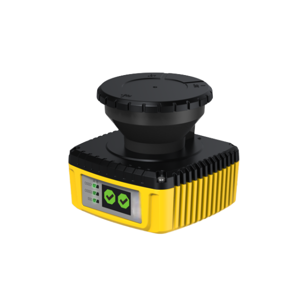
AGV & AMR Safety Risks — How Safety Laser Scanners Protect Your Operations
A safety laser scanner is an electro-sensitive protective device that creates a “fingerpint” in the air by projecting a configurable curtain of time-of-flight (ToF) laser pulses. When anything – personnel, obstacle, another vehicle – penetrates that protection field, the sensor instantly outputs a safety-rated OSSD signal to the AGV PLC, making a controlled hold or slowdown possible before impact occurs. Unlike presence-sensing barriers, that creates a set and forget physical obstacle between the vehicle and the load, the laser scanner generates a safety zone task-specific to the AGV path.
The Real Cost of Inadequate AGV Safeguarding
Automated guided vehicles on the modern factory floor or warehouse have established a specific risk profile that the safety scanning market must address. AGVs travel between 1.5 m/s and 3 m/s in shared spaces with humans present — fast enough to do harm, slow enough that a human doesn’t expect that harm to be possible. The hazards fall into three broad categories: safety-related personnel injury, compliance liability, and the time and cost impacts of false stops due to unoptimized safety standards configuration.
Industry surveys from the many hundreds of forklift and AGV installations fielded since 2004 show that good safety scanning has effectively eliminated vehicle collision problems downrange of 70% and even 90% vs sites which relied on warning horns alone for obstacle detection. But even cost of safety-related personnel injury, the legal exposure is unavoidable. ISO 3691-4:2020 mandates driverless industrial truck inspection for functional safety-rated area protection. IEC 61496 Type 3 specifies the exact test parameters a safety laser scanner must pass to qualify for this purpose.
Pain
AGV strikes worker or infrastructure, triggering injury, OSHA citation, and production halt.
Cause
No certified area protection, or scanner misconfigured with zones that don’t match actual travel speed and stopping distance.
Solution
SIL 2 / PLd Cat 3 safety laser scanner with application-specific zone configuration — protection field sized to AGV braking distance at operational speed.
Proof
70–90% collision incident reduction in documented AGV deployments after certified area scanner installation.
Regulatory Liability: What the Standards Actually Require
Having a ceiling performance test specification, IEC 61496-3 defines the only minimum laser scanning requirement for a Type 3 field scanning laser device – constructs image, dual beam OSSD driver outputs, autodiagnostics, and defined response specification. ISO 3691-4 lays out the specification the AGV provider or end-user must perform: a prioritization of the using a risk analysis and choosing a safety device that complements that analysis in accordance with safety integrity level analysis. A scanner without IEC 61496 Type 3 certification is an avoidable liability risk.
The False Stop Problem
One operational safety risk that is routinely underappreciated is the false stop — a safety stop caused by rack reflections, spontaneous object movement, the reflection from dynamically reconfigured warehouse geometry or obstacle mitigation, or a momentary flash of sunlight. In a busy warehouse AGV environment, a false stop rate of 2-3 per hour can have an effective throughput impact of 15-20%. A properly engineered scanner with multi-reflection suppression, configurable field shapes, and capable of functioning in daylit environments is far from a optional feature but a critical component of good factory economics.
“We design every CCH scanner’s optical assembly around the false-stop problem first. The safety certification is the baseline requirement – but a scanner that trips repeatedly in a real warehouse is not a working safety solution, it’s a throughput obstacle.”
CCH Safety Laser Scanner Series — Models & Selection Guide
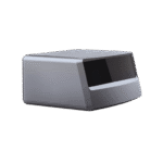
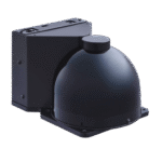
CCH Sensing offers three scanner lines that cover the entire range of AGV and AMR safety applications a compact autonomous mobile robot using narrow warehouse aisles, to an outdoor forklift requiring IP67 ingress protection and long detection range. Every model is shipped with a Windows based configuration application for zone deployment, and all hold IEC 61496 Type 3 certification, with SIL 2 / PLd Cat 3 documentation.
Indoor AGV
CCH-SLS 200
Smallest form factor for warehouse AGVS and AMRs operating at up to 1.8 m/sec. in structured indoor environments.
- Protection Range 3 m
- Warning Range 20 m
- Opening Angle 270°
- Min. Object Size 70 mm
- Response Time ≤ 80 ms
- Protection Zones Up to 4 simultaneous
- Ingress Protection IP54
- Interface OSSD ×2, RS-422
- Certification IEC 61496-3, SIL 2, PLd
Production AMR
CCH-SLS 500
Mid-range scanner for production hall AMRs and collaborative robot systems requiring multiple reconfigurable safety zones.
- Protection Range 5.5 m
- Warning Range 30 m
- Opening Angle 275°
- Min. Object Size 70 mm
- Response Time ≤ 60 ms
- Protection Zones Up to 8 simultaneous
- Ingress Protection IP65
- Interface OSSD ×2, EtherNet/IP, RS-422
- Certification IEC 61496-3, SIL 2, PLd Cat 3
Outdoor Forklift AGV
CCH-SLS 900
Heavy-duty for outdoor AGV operations port logistics, yard transport, and outdoor forklift automation in changing light and rain conditions.
- Protection Range 9 m
- Warning Range 40 m
- Opening Angle 275°
- Min. Object Size 70 mm
- Response Time ≤ 80 ms
- Protection Zones Up to 16 simultaneous
- Ingress Protection IP67
- Interface OSSD ×2, PROFINET, RS-422
- Certification IEC 61496-3, SIL 2, PLd Cat 3, IEC 62998
Full Technical Comparison — CCH SLS Series
| Parameter | CCH-SLS 200 | CCH-SLS 500 | CCH-SLS 900 |
|---|---|---|---|
| Protection Range (m) | 3 | 5.5 | 9 |
| Warning Range (m) | 20 | 30 | 40 |
| Opening Angle (°) | 270 | 275 | 275 |
| Angular Resolution (°) | 0.3 | 0.1 | 0.1 |
| Min. Object Detection (mm) | 70 | 70 | 70 |
| Response Time (ms) | ≤ 80 | ≤ 60 | ≤ 80 |
| Simultaneous Zones | 4 | 8 | 16 |
| Ingress Protection | IP54 | IP65 | IP67 |
| Weight (g) | ~680 | ~850 | ~1200 |
| Laser Class | Class 1 | Class 1 | Class 1 |
| SIL Level | SIL 2 | SIL 2 | SIL 2 |
| Performance Level | PLd Cat 3 | PLd Cat 3 | PLd Cat 3 |
| Outdoor Certified (IEC 62998) | No | No | Yes |
Safety Laser Scanner Selection Matrix for AGV Applications
Industry Authority Reference — CCH Sensing Engineering| AGV / Application Type | Recommended Model | Protection Range (m) | Opening Angle (°) | Angular Res. (°) | IP Rating | Key Reason |
|---|---|---|---|---|---|---|
| Warehouse AGV (indoor, narrow aisle) | CCH-SLS 200 | 3 | 270 | 0.3 | IP54 | Compact size, 4 zones, cost-effective for ≤1.8 m/s |
| Production floor AMR (multi-zone) | CCH-SLS 500 | 5.5 | 275 | 0.1 | IP65 | 8 simultaneous zones for dynamic cell environments |
| Collaborative robot cell perimeter | CCH-SLS 500 | 5.5 | 275 | 0.1 | IP65 | 0.1° resolution for precise zone boundary at robot reach |
| Outdoor forklift AGV (yard / port) | CCH-SLS 900 | 9 | 275 | 0.1 | IP67 | IEC 62998 outdoor cert, 40 m warning zone at high speed |
| Food/pharma (washdown environment) | CCH-SLS 900 | 9 | 275 | 0.1 | IP67 | IP67 resists cleaning chemicals, no dust contamination |
Have a non-standard AGV configuration high speed, irregular travel path, dual-scanner install?
Get Custom Configuration QuoteSafety Laser Scanner vs Safety Mats, Light Curtains & Hard Guarding
Procurement teams for AGV and AMR systems calculating access protection compare four technology categories. The table below uses actual measured or summarized published data no qualitative designations such as High / Medium / Low to enable your engineering and management teams to do a head-to-head comparison for your requirements.
| Criterion | Safety Laser Scanner | Safety Mats | Light Curtains | Hard Guarding (fencing) |
|---|---|---|---|---|
| Detection Area Shape | Configurable polygon, up to 16 zones | Fixed rectangle (mat footprint) | Linear plane only | N/A — physical barrier |
| Typical Purchase Price (USD) | $800 – $5,000 | $200 – $800 per mat section | $600 – $3,000 | $500 – $5,000+ installed |
| AGV Travel Path Compatible | Yes — mounts on AGV, travels with vehicle | No — stationary floor-mount only | No — fixed linear plane | No — prevents AGV movement |
| Reconfigurability | Software zone edit, ≤ 30 min per change | Physical relocation, mat cutting required | Bracket repositioning, ≥ 2 hrs | Structural modification, days |
| Performance Level Achievable | PLd Cat 3 / SIL 2 (IEC 61496 Type 3) | PLe Cat 3 (IEC 61496-1, pressure-sensitive) | PLe Cat 4 (IEC 61496-2, Type 4) | PLd achievable with access interlocks |
| Maintenance Interval | Annual optical window cleaning; no consumables | Mat surface wear; replace every 2–5 years | Emitter/receiver alignment check; annual | Hinge and latch inspection; annual |
| 5-Year Consumable Cost | ~$0 consumables; 1 window cleaning/yr | Mat replacement: $1,000 – $4,000 | Low — beam alignment only | Hinge/lock hardware: $200–$800 |
| False Stop Risk in Dynamic Env. | Manageable with multi-path suppression & zone tuning | High — floor debris, liquid spills trigger mat | Low — clean factory setting | N/A — not a sensor |
The pattern above reveals one theme: safey laser scanners are the only technology that rides along with the AGV, establishes a variable detection field around the machine, and remains reconfigurable as your environment/area changes. Safety mats are limited to preventing access to an unchanging floor zone, and suffice for stationary robotic cell access protection – they will not work for a moving vehicle. Light curtains throw up a plane of detection suited for stop proximity guarding and conveyor access, not area protection for autonomous mobile robots. Hard guarding physically prevents access and proves necessary for a high risk area where employee entry must be a deliberate unlocking action.
Any AGV or AMR that operates in a shared human- machine environment and shifts travel paths will not find a suitable safety device in the three other categories a safety area scanner is also not in competition with. It is the one that exists as a viable option, for the application.
5-Year Total Cost of Ownership — Safety Laser Scanner vs Safety Mats
Based on the industry implementation experience of AGV integration projects, safety laser scanners yield a significantly better TCO over a 5-year period when used in this mobile vehicle environment. Scanner purchase prices have dropped roughly 50% over the last ten years , while ongoing safety mat replacement costs persist through surface wear form vehicle traffic and fork tine contact. A new mid-sized warehouse operating 10 AGVS with mat protection will regularly spend $2,000-$4,000 for safety mats in 3 years comparable to the purchase cost of 10 new scanner units.
Real-World AGV & AMR Applications Across Industries
Safety laser scanners are required to operate in considerably different environments in different industries. The table presented below maps the particular challenge each industry faces, how a correctly configured scanner meets that challenge, and which key technical spec drives its selection. All results are representative of typical applications for each industry on the whole – not specific CCH customer projects.
Warehouse & Logistics
Automated Guided Vehicles in High-Throughput Distribution Centers
Challenge
Forklifts operating in the aisles with AGV traffic demand minimum clearance in order to operate efficiently. Narrow aisle environments found in typical warehouse settings, with widths as narrow as 2.5 m, demand the tightest possible margin of error.
Solution
Modules installed in the corners of AGV protect zones can be automatically opened and closed in real time while travelling through aisle pinch points with a 270-275 field of view scanner, mounted on the front corner of the vehicle. AGV controller detects entering and exiting of narrow aisles and switches zone fields accordingly.
Automotive Manufacturing
AMRs and Material Transport in Body Shop Environments
Challenge
Blue-light welding flash, metal dust, reflective surfaces and heat generation can hide the presence of other AGVs, handheld tooling and humans in automotive body shop environments. In addition, the automation of delivering materials to the paint condition requires AGVs that do not frequently stop or slow.
Solution
Multi-echo processing capabilities and reflective surface suppression techniques used in optimum automotive body shop scanner configurations maintain safe operating detection even when exposure to welding is high. Multiple field sets enable a robot AGV to shrink its working zone at line speed as long as the path is confirmed visually clear.
Electronics & Semiconductor
Cleanroom AGVs for Wafer and Component Transport
Challenge
AGVs entering and leaving cleanroom environments must meet classification standards at entry. Scanners must be free from particulate generation, function well under fluorescent and UV lighting used inside the cleanroom, function under the UV lighting used to sterilize equipment afterward, and provide interfaces compatible with the cleanroom-qualified AGV control system.
Solution
Class ISO 5 cleanroom entry and exit requirements met with laser Class 1 scanners that have sealed optical housings and exterior contours to facilitate cleaning with IPA. General purpose a 24V OSSD outputs connect directly to a time-tested safety PLC platform in a semiconductor AGV.
Food & Pharmaceutical
AGVs in Washdown and Hygiene-Sensitive Production Areas
Challenge
Washdowns in the pharmaceutical and food processing industries expose equipment to high levels of cleaning chemicals and soap suds. If AGV-mounted sensors are to survive this environment, their seals and optics should not be compromised once exposed to repeated chemical assaults.
Solution
Sealed IP67-rated scanner bodies with chemical resistant seals ensure at least 1000 wash cycles before fogging and degradation occurs. Heated window options prevent dew collection during cold storage in temperature cycling applications. Full platform scanners with QS and IO-Link monitor zone configuration to match conveyor and pallet arrangements.
Port & Outdoor Logistics
Outdoor Forklift AGVs and Container Yard Automation
Challenge
Parking lot and loading dock environments place laser safety sensors outside in the sunlight, exposed to passing rain, and subject to false triggering from background objects such as grasses, driveways, puddles and gravel. Indoor-focused scanners with ambient light rejection performance specifications fail IEC 62998 test standards when exposed to these conditions.
Solution
IEC 62998-qualified scanners with a near-IR laser wavelength (around 905 nm) and suppression algorithms designed to eliminate detection of clutter in the background. 9 m protection zone range and 40 m warning zone range provides a long stopping margin for outdoors-mounted forklift AGVs traveling up to 3 m/s.
Having a specific industry use case not included above – hazardous area, ATEX zone, or high-speed rail AGV?
Discuss Your ApplicationCertifications, Pricing & How to Order — Complete Procurement Guide
For procurement teams seeking safety laser scanners for AGV integration, this covers the certification matrix, pricing, OEM process, and post-sale support — the entire business case.
IEC 61496 Type 3
SIL 2 (IEC 61508)
PLd Cat 3 (ISO 13849)
ISO 13849-1
CE Marked
IEC 62998 (Outdoor)
What Each Certification Means for Your AGV Integration
IEC 61496 Type 3 — Area Scanning Sensor (AOPDDR)
The fundamental standard for active opto-electronic protective devices using diffuse reflection. Type 3 specifies minimum performance (object of 70 mm at rated range, black body detection at 1.8% reflectivity), OSSD output requirements, self-test cycles, and IEC 61496-3 black body testing at 1.8% reflectivity. Any scanner lacking IEC 61496 Type 3 should not be selected as the primary safeguard on an AGV under ISO 3691-4.
SIL 2 — Safety Integrity Level (IEC 61508)
SIL 2 levels indicate that there is 10 to 10 dangerous failure on demand. In a single-channel safeguarding application such as a safety laser scanner on an AGV, SIL 2 is the appropriate level for the few warehouse AGVs moving below 3 m/s.
PLd Cat 3 — Performance Level d, Category 3 (ISO 13849-1)
PLd Cat 3 means that human detection is implemented using two independent channels (dual-channel OSSD), and a single component failure will not cause the safety function to be lost. This is the minimum level of protection required for human detection for most AGV applications under ISO 3691-4.
Engineering Note — The IEC 61496 Certification Floor
All safety laser scanners – from established European brands as well as CCH – are designed and built according to the same IEC 61496-3 ceiling. The physics and the IEC 61496-3 certification life cycle is exactly the same. A scanner receives IEC 61496 Type 3 certification by passing the same test plane, in any country: black body detection at 1.8% reflectivity, time of-flight definition, dual-channel OSSD, self-test cycles validated. Your CE and ISO 3691-4 approved compliance file uses the certification document, not the brand label on the scanner.
Pricing — What Drives Safety Laser Scanner Cost
The range of prices for safety laser scanners depends on the specifications and certifications you are seeking. OEMs have different needs regarding volume, application details, and integration support. Instead of pricing from a published catalog, we will provide a custom quote. Factors influencing pricing include:
Detection range
longer detection range needs more powerful optics and heavier video signal handling
Number of simultaneous protection regions
4-zone models are cheaper than 16-zone ones
Ingress rating
IP67 outdoor-rated assembled housing costs more than IP54
Fieldbus interface
Ethernet/IP or PROFINET add to the cost versus SimpleRS422
Certification pack
IEC 62998 outdoor operation costs more test time
Order quantity
default prices are based on an OEM purchase volume of 100+ units/year
In general, well-established safety laser scanner products are widely available from automation distributors in the $800-900 price range depending on the above criteria. CCH Sensing OEM pricing is comparable at volume quantities; call us for a quick quote on the model you select.
OEM Process — From Initial Inquiry to Production Delivery
01
Consult
Send us your AGV specifications and expected operating conditions, and anticipated certification needs. One of our application specialists will develop a recommended default model.
02
Customize
Confirm housing color, branding, zone configuration defaults, interface type (OSSD, RS-422, fieldbus), and packaging requirements.
03
Sample
Receive 2-5 pre-production samples for mechanical fit, zone configuration validation, and integration testing. Typical sample lead time: 15-25 days.
04
Production
Mass production with full IQC, final functional test, and certification documentation per unit. Typical production lead time: 30-45 days at volume.
After-Sales Support
Every CCH safety laser scanner ships with a 24-month warranty against manufacturing defects. Technical support is available in English via email and video call for integration, zone configuration, and safety PLC interface questions. Spare optical windows, mounting brackets, and interface cables are stocked at our Hangzhou facility with DHL express shipment available. For OEM partners managing installed base service, we provide private-label technical documentation and firmware update packages.
"We know that OEM customers stake their own product quality on our components. That is why every CCH scanner goes through the same IEC 61496 test protocol - including the 1.8% black body detection test - regardless of whether it carries our label or yours. The certification file that ships with the unit is the same document your customer's safety auditor will check."
Frequently Asked Questions About Safety Laser Scanners for AGV
Most modern AGVs use safety laser scanners as their primary area protection device, supplemented by bump sensors or safety edges at the vehicle bumper as a last-resort contact-detection backup. Safety laser scanners provide the pre-contact detection that ISO 3691-4:2020 requires - detecting a person or obstacle within the protection zone before physical contact occurs. Some AGVs also use 3D depth cameras for navigation, but these are not safety-rated devices and cannot substitute for an IEC 61496 certified scanner in a compliance-required installation.
Safety laser scanner prices vary from approximately $800 for compact indoor models to $5,000 for long-range outdoor units with advanced fieldbus interfaces - based on widely available market pricing from industrial automation distributors. CCH Sensing pricing for OEM volumes is competitive within this range. The factors that drive cost upward are detection range, number of simultaneous configurable zones, IP rating, fieldbus interface (PROFINET/EtherNet/IP vs RS-422), and IEC 62998 outdoor certification. Contact us for a volume-specific quotation - we provide pricing by model and annual order quantity.
The primary standards chain for AGV safety scanners is: IEC 61496-3 (Type 3 AOPDDR - the sensor-level standard defining detection performance and self-test requirements), IEC 61508 (functional safety framework for SIL 2 quantification), and ISO 13849-1 (machinery safety - PLd Cat 3 architecture). The vehicle-level standard requiring certified area protection is ISO 3691-4:2020 for driverless industrial trucks. In North America, ANSI/RIA R15.08 applies to industrial mobile robots. All CCH Sensing safety laser scanner models carry IEC 61496 Type 3, SIL 2, and PLd Cat 3 certification with CE marking.
Safety laser scanners provide raw scan data outputs through the RS-422 or fieldbus interface along with their safety OSSD outputs, and an AGV platform may process this data to provide localization- SLAM navigation uses the same 2D scan map produced by the safety function. However, the safety and navigation functions should be architecturally isolated: the safety OSSD output is certified, while the navigation data stream is informational only. Use of the safety scanner scan data for navigation is common practice and does not compromise safety as long as the connection to the safety PLC is limited to the OSSD channels.
The key difference is the certification and output architecture. An ordinary lidar sensor (such as might be used for AGV mapping and navigation) produces a point cloud or a distance array- it has no certified safety output. A safety laser scanner provides IEC 61496-certified dual-channel OSSD signals that a safety PLC or safety relay can use to initiate a machine safety stop. A safety scanner's internal architecture includes self-test cycles, redundant detection channels, and systematic failure-detection logic required by IEC 61508. An ordinary lidar, regardless of its detection precision, cannot replace a safety scanner in an application requiring certified area protection.
Selection proceeds through four parameters in sequence: (1) Protection range- size the protection field to cover the AGV stopping distance at maximum operational speed plus a safety factor. At 1.5 m/sec with typical AGV braking, a 3 m protection field provides approximately 2 seconds of detection time. (2) Opening angle- 270-275 covers front and both sides from a single corner-mounted scanner; 190 models require dual-scanner arrangements to cover all sides of the vehicle. (3) IP rating- IP54 for standard warehouse environments, IP65 for production facilities with routine cleaning, IP67 for outdoor or washdown applications. (4) Zone count- choose a model with at least as many zones as your AGV takes at top speed plus one maintenance mode zone. Use the CCH selection matrix above or call our applications team and we will develop a guided recommendation.
Yes. CCH Sensing builds safety laser scanners OEM customers who apply their own brand and housing colors. OEM services include custom label printing, house color (RAL matching available), default zone configuration at time of shipment, private-label user manual and certification documents, and custom packaging. Minimum OEM order quantities vary by model, but are typically 50-100 pieces per production run. We assist OEM customers by dedicated technical account managers and providing supply chain documents (MSDS, RoHS, REACH, country-of-origin certificates) required for customs clearance and product compliance.
Standard model orders (CCH-SLS 200, 500, 900 without customization) leave factory within 15-20 business days of order receipt for quantities up to 50 pieces. For OEM orders requiring logo customization or zone pre-configuration, add 10-15 days for sample approval plus 30-45 days for production. For time-sensitive AGV installations, we can often expedite production- contact us with your desired delivery date and we will confirm lead-time. All shipments include equipment verification and IEC 61496 Type 3 calibration certificates for each piece.
Ready to Specify Safety Laser Scanners for Your AGV Project?
Send us your AGV specifications - ride speed, operating environment, zone coverage requirements and production volume and application engineering team will recommend the appropriate CCH SLS model with a same-day reply.
Request Quote Now
Trending now