Get in touch with QJKH Company
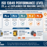
If you build or buy machinery for the European market, the ISO 13849 performance level is the number that decides whether a safety function is reliable enough to trust. Performance Level (PL a to PL e) under EN ISO 13849-1 puts a measurable reliability target on every safety-related control function, from a guard interlock to an emergency stop. This guide walks through what each PL means, how to determine the required PL, how the hardware actually reaches it, and how to prove it on paper, alongside our own worked example of a PL e function. For the wider picture, see our overview of machine safety standards.
Quick Specs: ISO 13849 Performance Level
| Standard | EN ISO 13849-1:2023 (Part 1, design) + ISO 13849-2 (validation) |
| PL scale | PL a (lowest) to PL e (highest), 5 discrete levels |
| What PL measures | PFHd (PFH) — average probability of a dangerous failure per hour |
| PL e band | ≥10⁻⁸ to <10⁻⁷ dangerous failures/hour |
| Set by | Category + MTTFd + DCavg + CCF (the four levers) |
| Updated | May 2026 (covers ISO 13849-1:2023 + EU Machinery Regulation 2027) |
What Is a Performance Level (PL) in ISO 13849-1?

Under ISO 13849-1, a Performance Level (PL) is a discrete level, one of five, from PL a to PL e, used to specify the ability of the safety-related parts of a control system (SRP/CS) to perform a safety function under foreseeable conditions. It is expressed as the average probability of a dangerous failure per hour, written PFHd in the 2015 edition and PFH in the 2023 edition.
In plain terms, PL answers one question: when this control system is asked to stop the hazard, how likely is it to fail dangerously?
Any control action that brings a machine to a safe state is a safety function: stopping a press when a hand crosses a light curtain, or preventing restart while a guard door is open. ISO 13849-1 applies regardless of the technology that carries it: electrical, electronic, programmable, hydraulic, pneumatic, or mechanical. Part 1 covers the design and the calculation of PL; Part 2 covers validation. The required PL is assigned during machine guarding risk assessment, before any hardware is chosen.
💡 Pro Tip
PL is a property of a whole safety function, not a single sensor. A PL e sensor wired into a single non-redundant output does not give you a PL e function — the weakest subsystem caps the result.
The Five Performance Levels: PL a to PL e and Their PFHd Bands

Each Performance Level corresponds to a band of dangerous-failure probability. PL e demands a PFHd between 10⁻⁸ and 10⁻⁷ per hour, the most reliable of the five, while PL a sits between 10⁻⁵ and 10⁻⁴, roughly one dangerous failure in 10,000 to 100,000 hours. The higher the assessed risk, the higher the PL you must reach.
| Performance Level | PFHd (per hour) | Risk reduction | Typical use |
|---|---|---|---|
| PL a | ≥10⁻⁵ to <10⁻⁴ | Low | Minor, reversible-injury hazards |
| PL b | ≥3×10⁻⁶ to <10⁻⁵ | Low–medium | Low-risk guarding |
| PL c | ≥10⁻⁶ to <3×10⁻⁶ | Medium | Type 2 light curtains, SIL2/PLc devices |
| PL d | ≥10⁻⁷ to <10⁻⁶ | Medium–high | Safety laser scanners (Type 3, PLd) |
| PL e | ≥10⁻⁸ to <10⁻⁷ | High | Type 4 light curtains, presses, robot cells |
Source: ISO 13849-1 (PFHd / PFH bands), cross-checked against published functional-safety references.
How to Determine the Required Performance Level (PLr): The Risk Graph
Before you choose any hardware, you determine the required Performance Level (PLr) for each safety function. ISO 13849-1 uses a risk graph in Annex A, and it turns on three parameters. We call it the 3-Parameter PLr Risk Graph: you read severity, then frequency, then avoidance, and the path lands on a PLr from a to e.
The 3-Parameter PLr Risk Graph (Annex A)
- S, Severity of injury. S1 = slight, normally reversible; S2 = serious, normally irreversible or fatal.
- F, Frequency and/or exposure. F1 = seldom and/or short exposure; F2 = frequent to continuous and/or long exposure.
- P, Possibility of avoiding the hazard. P1 = possible under specific conditions; P2 = scarcely possible.
A serious, frequently exposed hazard that’s hard to avoid (S2, F2, P2) lands on PLr e. The 2023 edition adds a structured A/B/C sub-determination to make the P parameter less subjective.
How Do You Determine the Performance Level in Accordance with EN ISO 13849-1?
You start from the machine without its safety measures and run a risk assessment to ISO 12100, which is the upstream Type A standard that feeds the inputs. For each hazard you define a safety function, then walk the S, F–P graph to get its PLr. That number becomes the target.
Industry practitioners frequently report that the hardest part is not the graph itself but drawing the boundary of each safety function, split one hazard into two functions and you can skew the whole PLr. Document every S/F/P choice; ISO 13849-1 assumes a worst-case exposure unless you can justify and record otherwise.
How a Performance Level Is Achieved: Category, MTTFd, DCavg and CCF
Once you know the PLr, you design hardware that meets it. The achieved PL comes from four levers working together, what we call the 4-Lever PL Architecture: Category (structure), MTTFd (component reliability), DCavg (diagnostics), and CCF (resistance to common-cause failure). A strong architecture alone doesn’t earn a high PL; all four must hold up.
Category describes the structure and its behaviour under a fault. Category B is the basic state of the art. Category 1 adds well-tried components and well-tried safety principles. Category 2 adds periodic automatic testing. In Category 3, a single fault doesn’t cause loss of the safety function (the channel is redundant). Category 4 adds that the fault is detected at or before the next demand. MTTFd (mean time to dangerous failure) is banded as low (3–10 years), medium (10–30 years), and high (30–100 years); for electromechanical parts it’s derived from MTTFd = B10d / (0.1 × nop). DCavg (average diagnostic coverage) is the ratio of detected dangerous failures to total dangerous failures. CCF (common cause failure) is scored by the point method in Annex F of ISO 13849-1.
| Category | DCavg | MTTFd | Achievable PL |
|---|---|---|---|
| Category B | None | Low | PL a |
| Category B | None | Medium | PL b |
| Category 1 | None | High | PL c |
| Category 2 | Low–Medium | Medium | PL c |
| Category 2 | Low–Medium | High | PL d |
| Category 3 | Low–Medium | Medium | PL d |
| Category 3 | Low–Medium | High | PL d–e |
| Category 4 | High | Medium | PL d–e |
| Category 4 | High | High | PL e |
Simplified from the ISO 13849-1 Category/MTTFd/DCavg relationship (Figure 5). Exact PL also depends on the measured DCavg value and a CCF score of at least 65 points.
📐 Engineering NoteCCF must score at least 65 of 100 points using the Annex F checklist (separation, diversity, protection against over-voltage and contamination, and so on). Miss the 65-point floor and a redundant Category 3 or 4 architecture can’t claim its target PL, no matter how good MTTFd looks.
A Worked Example: Building a PL e Safety Function
To make the four levers concrete, here’s how a complete PL e access-guarding function is built from our own devices. The safety function is “stop the press when a hand enters the danger zone.”
- ✔Input (sensing): a Type 4 safety light curtain with 14 mm finger resolution and a response time of ≤14 ms, rated SIL3 / PL e under IEC 61496-1/-2.
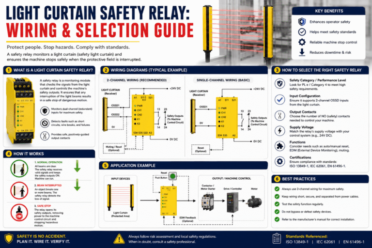
- ✔Logic: a dual-channel safety relay module with a response time of <20 ms, rated SIL3 / PL e, processing the OSSD signals.
- ✔Output: two force-guided contactors with feedback monitoring (EDM), giving the redundant, monitored output a Category 4 structure.
Each subsystem carries its own PFHd; the function PFHd is the sum, and it must land in the PL e band. Two design checks decide success. First, every subsystem has to reach PL e, a PL e curtain on a single non-redundant contactor would drop the function to PL c, because the weakest subsystem governs the result. Second, the response times add up: the ≤14 ms curtain plus the <20 ms relay plus contactor delay form the total stopping time, which feeds the minimum safety distance through ISO 13855 (S = K × T + C). If you mount the curtain too close, the function can be PL e on paper yet still let a hand reach the hazard before the press stops. Run the numbers with our ISO 13855 safety distance calculator before you fix the mounting position.
Performance Level vs SIL: ISO 13849 vs IEC 62061
PL is not the only integrity yardstick. IEC 62061 uses the Safety Integrity Level (SIL), inherited from IEC 61508. The two are related but not interchangeable: ISO 13849 is architecture-based and covers every technology, while IEC 62061 is more probabilistic and historically focused on electrical, electronic, and programmable control. For machinery, IEC 62061 defines SIL 1 to SIL 3 only, there is no SIL 4. The PL-to-SIL Equivalence Crosswalk below maps the levels.
| ISO 13849 Performance Level | IEC 62061 SIL (machinery) | PFHd band (per hour) |
|---|---|---|
| PL a | (no SIL) | ≥10⁻⁵ to <10⁻⁴ |
| PL b | SIL 1 | ≥3×10⁻⁶ to <10⁻⁵ |
| PL c | SIL 1 | ≥10⁻⁶ to <3×10⁻⁶ |
| PL d | SIL 2 | ≥10⁻⁷ to <10⁻⁶ |
| PL e | SIL 3 | ≥10⁻⁸ to <10⁻⁷ |
Both standards were once meant to merge into a single document, IEC/ISO 17305, scheduled for around 2017. That project was abandoned, so machine builders still choose between ISO 13849 and IEC 62061 (the two are often used together when software plays a large role). In practice, most machinery safety functions are designed to ISO 13849 because the architecture-based method is quicker to apply. For a device-level view of how PL maps to hardware, compare Type 4 (PL e) versus Type 2 (PL c) light curtains.
Verifying and Validating the Achieved PL: SISTEMA and ISO 13849-2

Reaching a PL on paper is only half the job. ISO 13849-1 closes with a PLa ≥ PLr Verification Gate: the achieved Performance Level (PLa) must meet or exceed the required level (PLr). If it falls short, you improve the design, better components, higher diagnostic coverage, or a stronger category, and run the loop again.
“During a risk assessment, the minimum required performance level (PLr) is identified. Designers then confirm that the achieved level meets or exceeds it, followed by verification and validation to ensure the system works as intended.”
ROSS Controls, on the four-factor PL workflow
Most engineers run the calculation in SISTEMA, the free software from the IFA (the institute of the German Social Accident Insurance), which models the Category/MTTFd/DCavg/CCF chain and returns the achieved PL. Validation then follows ISO 13849-2, in the 2023 edition the normative validation requirements were folded into Part 1, though the fault-evaluation tables still live in Part 2. Keep a Safety Requirements Specification and a validation plan for the machinery technical file. To match a device to a target level quickly, our PL/SIL category mapper is a useful starting point.
How Do You Know If Your Safety System Truly Reduces Risk?
Honestly, you don’t know until verification and validation say so. Even a compliant-looking function can fail an audit because a step was skipped: a fault exclusion that wasn’t justified, a diagnostic coverage value claimed but not measured, or a CCF checklist left incomplete.
The defensible position is documented evidence, the PLr determination, the SISTEMA calculation, the validation record, and the test results, that shows PLa ≥ PLr for every safety function. For help choosing the logic device, see our safety relay module selection guide.
Industry Outlook: ISO 13849-1:2023 and the 2027 EU Machinery Regulation

The 2023 fourth edition of ISO 13849-1 reworked several areas: it treats a safety function as a combination of “subsystems” (the term that now stands in for SRP/CS), adds a new clause on software safety requirements, folds validation in from Part 2, and gives Annex A a structured A/B/C method for the P parameter. EN ISO 13849-1:2023 was cited in the Official Journal of the European Union in May 2024, and EN ISO 13849-1:2015 is set to be withdrawn after a transition period ending 15 May 2027.
Two dates matter for anyone selling into Europe. The EU Machinery Regulation (EU) 2023/1230 replaces the Machinery Directive 2006/42/EC and applies from 20 January 2027, which makes the practical transition for the 2015 edition shorter than the 2027 withdrawal date alone suggests. Not everyone welcomes the new edition, and the debate is worth knowing:
“I strongly recommend that you do not use ISO 13849-1:2023, as the standard has serious technical flaws… I recognize that consensus processes do not always satisfy all stakeholders.”
Doug Nix, Machinery Safety 101
That’s one recognized expert’s documented position, not a consensus; the edition is officially harmonized and most builders will adopt it. On the technology side, integrated safety networks such as Safety over EtherCAT (FSoE) increasingly carry safety signals over a standard fieldbus using a black-channel approach, reaching SIL3 / PL e without discrete relay wiring. The action for machine builders is concrete: re-validate your safety-related control systems against the 2023 edition and confirm your conformity route under Regulation 2023/1230 before January 2027, rather than at the deadline.
Why We Wrote This
As a manufacturer of Type 4 light curtains, safety laser scanners, and safety relay modules, we map products to ISO 13849 Performance Levels every day, our Type 4 curtains and relay modules are rated SIL3 / PL e, our laser scanners PL d. The worked PL e example above reflects the device data we publish, not a generic template. Reviewed by the CCH Shanghai Sensing Intelligence Technology Co., Ltd technical team.
Frequently Asked Questions
Q: What is the difference between Performance Level (PL) and SIL?
View Answer
PL comes from ISO 13849-1 and runs from PL a to PL e; SIL comes from IEC 62061 (and IEC 61508) and runs from SIL 1 to SIL 3 for machinery. Both express the reliability of a safety function, but ISO 13849 is architecture-based and covers all technologies, while IEC 62061 is more probabilistic and electrically focused. PL e maps to SIL 3. The two are related, not interchangeable, and often used together when software is involved.
Q: How do you determine the required Performance Level (PLr)?
View Answer
You run the machine through the ISO 13849-1 Annex A risk graph for each safety function, scoring three parameters: severity of injury (S1 or S2), frequency or exposure (F1 or F2), and possibility of avoidance (P1 or P2). The combination assigns a required PL from a to e. A serious, frequently exposed, hard-to-avoid hazard lands on PLr e. The assessment is done as part of an ISO 12100 risk assessment, before any hardware is selected.
Q: What does PFHd mean in ISO 13849-1?
View Answer
PFHd is the average probability of a dangerous failure per hour, the metric behind every Performance Level. The 2015 edition labels it PFHd (“probability”); the 2023 edition uses PFH (“average frequency”). Each PL maps to a band: PL d sits between 10⁻⁷ and 10⁻⁶ per hour, and PL e between 10⁻⁸ and 10⁻⁷. A lower PFHd means a more reliable safety function.
Q: Can ISO 13849 and IEC 62061 be used together on the same machine?
View Answer
Yes. Both are harmonized Type B standards, and many projects use ISO 13849 for most functions and IEC 62061 where complex programmable electronics or software dominate. You document which standard each function follows, and a single machine can legitimately mix the two approaches across its different safety functions.
Q: Does ISO 13849-1:2023 change how Performance Level is calculated?
View Answer
The core Category / MTTFd / DCavg / CCF method stays. The 2023 edition restructures the document around subsystems, adds software safety requirements, integrates validation from Part 2, and refines the Annex A parameter-P determination with an A/B/C method. Existing PL calculations remain valid, but the design and documentation steps are clarified.
Q: What is MTTFd in ISO 13849?
View Answer
MTTFd is the mean time to dangerous failure of a channel, banded as low (3–10 years), medium (10–30 years), or high (30–100 years). For electromechanical parts it is derived from the B10d value and the number of annual operations, and a higher MTTFd helps push the channel toward a higher PL.
Q: Is a higher Performance Level always better?
View Answer
No. The goal is to meet the PLr, not exceed it for its own sake. Specifying PL e where PLr is PL c adds cost, wiring, and diagnostic demands, and can raise nuisance trips. A safety function not matched to its hazard is over-engineered — or, if under-scoped, dangerous.
References & Sources
- ISO 13849-1:2023, Safety of machinery, Safety-related parts of control systems, Part 1 — International Organization for Standardization
- SISTEMA & IFA Report 2/2017e, Functional safety of machine controls — IFA, German Social Accident Insurance (DGUV)
- Regulation (EU) 2023/1230 on machinery — Official Journal of the European Union
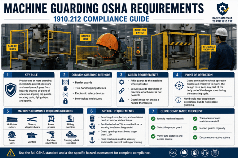
- 29 CFR 1910.212, General requirements for all machines — U.S. OSHA
- Global machine safety following IEC/ISO 17305 — ISA InTech
- US 9,356,415 B2, Safety control system referencing ISO 13849-1 Performance Levels — USPTO via Google Patents
Related Articles
Matching devices to a target Performance Level?
Our application engineers map your PLr to Type 4 light curtains, safety laser scanners, and SIL3/PL e relay modules, with free evaluation samples.