Get in touch with QJKH Company
Safety relay modules are the building blocks of machine safety circuits for manufacturing, packaging and process automation. Whether you are wiring an E-STOP for a single press brake or designing an entire multi-zoned safeguard on an automated assembly line, knowing how these devices operate — and how to specify one correctly — has direct implications on operator protection and compliance.
This article guides you through the architecture and wiring best practices of safety relay modules, their compliance ratings, and a practical choice framework for engineers and safety integrators.
Quick Specs – Safety Relay Modules:
| Standards | EN 50205, IEC 61508, ISO 13849-1, IEC 62061 |
| Safety Rating | Up to SIL 3 / PL e / Category 4 |
| Contact Type | Force-guided (mechanically linked NO + NC) |
| Channels | Single-channel or dual-channel (K1/K2) |
| Response Time | 10–30 ms typical |
| Supply Voltage | 24V DC (common), 24–240V AC/DC available |
| Mounting | 35 mm DIN rail, 22.5–45 mm width |
What Is a Safety Relay Module?
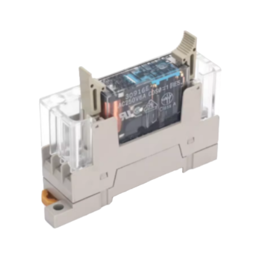
A safety relay module is a self-contained electromechanical device designed to monitor safety input signals — such as emergency stop buttons, safety gates, and light curtains — and reliably switch off hazardous machine outputs when a protective stop is triggered. Unlike standard relays, safety relay modules use force-guided contacts built to EN 50205 and incorporate redundant internal channels to achieve fail-safe operation.
Safety relay modules have a simple core function: they are placed between a protective device and a machine power contactor, and constantly check the inputs and internal operation for faults. When the inputs and internal logic are correct, they energize safety contacts and allow the machine to operate. If an input hazards occurs, or an internal fault is detected — such as contact welding — then the safety relay open the safety contacts and prevents the machine from running.
How is a safety relay different from a regular relay?
A standard relay might control a circuit but it doesn’t have any way of knowing if the relay has failed. A safety relay module has these other differences:
✔ Safety Relay Advantages
- Force-guided contacts per EN 50205 – physically linked NC and NO sets
- Redundant dual channels (K1 + K2) with cross-fault monitoring
- Weld detection on the contacts – prevents re-closure under a weld condition
- Certification to SIL 3 / PL e for safety critical uses
⚠️ Standard Relay Limitations
- No forced guidance — contacts can weld without detection
- Single channel only — one path of failure
- No internal diagnostics or fault memory
- Certification under IEC 61508 for general safety-control applications
These factors mean a safety relay module is a required minimum when safety risk assessment under ISO 12100 indicates a need for safety protection. For specific types of modules, see our safety relay module database.
How Safety Relay Modules Work — K1/K2 Redundant Contact Logic
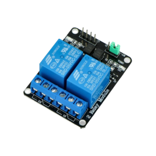
All dual-channel safety relay modules contain two independently energized internal relays, called K1 and K2. This dual-redundant relay design allows for two isolated contacts sets, which can then operate in conjunction to fail- safe in the event of overload or weld failure. If either relay COIL fails to energize as commanded, or if the internal feedback logic detects a mismatch between the K1 and K2 external contacts, then the safety relay is latched out and the equipment has to be reset and power cycled before operation.
What is K1 and K2 in a safety relay?
K1/K2 are the internal contactors of a dual relay safety module. K1 is activated by relay channel 1 (CH1). K2 is activated by relay channel 2 (CH2). Each contactor includes 2 normally open (NO) and 2 normally closed (NC) contacts. Both NO contacts of K1 and K2 sit in series with the machine contactor coil. Current flows only when both contacts energize. NC contacts link back into the internal control logic circuit.
Why this is important: if K1 contacts weld shut after several years of cycling, the K1 NC monitoring contact will not be closed. Internal monitoring detects this mismatch – K1 entered lock-open state while K2 entered the standby-release state, and the module will refuse to energize on your next start cycle. The machine must be attended until a trained technician removes and replaces the module. This is the fundamental principle of force-guided contacts as specified by EN 50205: the mechanical link between the NO and NC contact sets prevents both sets from being in the same state simultaneously.
“The safety relay contains internal dual redundant relays with series-connected normally-open contacts providing the safety output. The normally-closed contacts from these same relays are used in the feedback loop to detect faults such as contact welding.”
— Aaron Dahlen, MSEE, Senior Applications Engineer at DigiKey
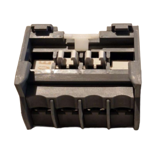
Signal path and terminal layout. Modern safety relay modules feature three terminal groups: input terminals (for safety sensors like E-stops or light curtains), output terminals (connect to contactors), and supply/feedback terminals. Modules can be wired with typical screw terminals—suitable for existing control panels, rated for wire gauge 0.2-2.5 mm—or quick-connect push-in terminals (faster wiring, no need for screwdrivers, for solid conductors up to 1.5 mm). The electromechanical switching element in most modules comprises physical relay coils. Solid-state safety modules are available for applications requiring faster switching time or handling higher switching frequency, though electromechanical modules’ modes of failure are well-understood and inherently detectable.
Pro Tip: Always check whether the response time listed on the safety relay datasheet accounts only for the relay’s internal switching time (about 10-20 ms) or includes the input filter delay as well. Actual signal-to-stop time ends up being the sum of safety relay relay response, contactor dropout delay, and mechanical brake activation.
Safety Relay Wiring — Practical Connection Guide
Wiring the safety relay incorrectly could result in machinery that fails to protect operators. This step-by-step example uses a typical dual-channel emergency stop arrangement–the most common safety wiring scheme on industrial machines.
E-Stop Wiring Sequence (Dual-Channel)
- Connect 24V DC to A1 (+) and A2 (). Watch for reversed polarity–your safely relay will not be damaged but will not energize.
- Wire Channel 1 take 24V and route it through the first NC contact set in your E-stop back to the input side of channel 1 (e.g. through S11). Add a return wire from channel 1’s input side (e.g. S12) back around through your safety monitor. This ensures you always have at least one independent shutdown path.
- Wire Channel 2 wire a second cable from your E-stop. route it through a second wire (have separate cable run from the second contact block in your E-stop at all times). Your dual channel system will never have both channels on the same terminal strip.
- Wire feedback loop: take a three-wire cable from the auxiliary NC contact set of your contactor’s auxiliary contact block and run it across your safety monitor channels to the following relay connections. This feedback allows the safety relay to hold off energizing until it knows the contactor is fully open.
- Wire safety outputs: run two wires between your NO contact set 1 (1314) and contactor coil; do the same for contact set 2 (2324). The relay will switch both sets of contacts in series to the contactor.
- Configure system reset: wire a momentary push button from the output of the relay to the input channel B; this will make system manual reset possible. For continuous operation, run a bridge connection from the relay channel A to channel B.
- Test: press the E-stop and verify that both contactor channels have dropped within the response time. Release the E-stop and check that both contactor channels energize only after pressing the reset pushbutton.
📐 Engineering Note — Wiring Parameters
- Wire gauge: 0.2-2.5 mm (AWG 24-14) for screw terminals; 0.14-1.5 mm for push-in.
- Supply: 24V DC ±15% (20.4–27.6V operating range)
- Dual channel agreement window; 200 ms – should inputs to CH1 and CH2 not open within 200 ms of each other module sets a discrepancy fault and locks out.
- Terminal designations are on IEC 60947-5-1 basis; S= safety input, Y= reset/feedback, pairs numbered are output contacts.
Single channel wiring (S11S12) use only – acceptable for Cat1 / PLc applications where one fault do not cause immediate danger e.g.a safety gate on a low energy machine with coasting time less than 2sec. Dual channel wiring (S11S12 + S21S22) necessary for Cat3 and Cat4 where a single wire break/ short shall not disable the safety function.
Reset configuration is important. Manual reset (Y1pushbuttonY3) is default and required for all but a handful of applications. Auto-restart (Y1 bridged to Y2) may only be used following a risk assessment shows automatic restart poses no additional hazard – uncommon case in a manned station. Note: the module IS THE SENSED EVENT – input sensing is falling-edge sensitive. The restart trigger is on the release Y1, not the press (opens) – allows operator to depower circuit breaker and still reset module by tying reset down.
⚠️ Common Mistake
Always use safety equipment – never jumper safety circuits during troubleshooting. Jumping S11 to S12 or shorting feedback loop to force restart is a good way to destroy safety chain and have no safety equipment left for testing your expensive system out of the box. If the module will not reset, the LEDs will tell you why – check input wiring and for welded contactor pin position wires before grabinga jumper wire.
Safety Relay vs Safety PLC vs Configurable Safety Controller
Choosing the right safety device is primarily a function of the complexity of your machine and the number of independent safety functions required. Below, a table compares the three main categories against the specific performance data to allow you to make an engineering decision.
| Feature | Safety Relay | Configurable Safety Controller | Safety PLC |
|---|---|---|---|
| Typical safety functions | 1–3 | 4–12 | 12–100+ |
| Configuration method | Wiring only | DIP switch / rotary selector | Software (certified IDE) |
| Typical response time | 10–30 ms | 15–50 ms | 20–100 ms |
| Approximate unit cost | $50–200 | $200–800 | $1,500–5,000+ |
| Diagnostic depth | LED status only | Basic fault codes | Full event logging |
| Scalability | Fixed | Modular expansion | Fully programmable |
| Best for | Single E-stop, simple gate | Multi-zone, moderate complexity | Complex interlocked systems |
💡 The 3/12 Function Rule
Count your safety functions; if less than 3 (say a single E-stop and a safety gate) individual relays are the most cost-effective. Between 3 and 12 safety functions use a configurable safety controller- reduces wiring and panel size. Over 12, a safety PLC with the certified programming environment is the practical choice for managing complex interlock logic, sequential startup, and zone-based control.
A common over-investment in safety is to specify a $3,000 safety PLC for a stand-alone machine with one emergency stop button and one safety gate – adds cost and complexity without improving safety. Two safety relays for $120 peak same SIL 3 / PL e safety rating at 8% of the $15,000 automation controller cost. Match technology to machine task.
Compliance — SIL, PL & ISO 13849 Ratings Explained

Two standards for functional safety ratings of safety relay modules. Knowledge of both is required: some industries reference one others the other – some safety projects demand both.
SIL (Safety Integrity Level) comes from IEC 61508 and its machine-specific derivative IEC 62061. SIL rates the probability of dangerous failure per hour (PFHd) on a logarithmic scale from SIL 1 (lowest) to SIL 3 (highest for standard machine applications). PL (Performance Level) comes from ISO 13849-1:2023 and rates safety performance from PL a (lowest) to PL e (highest), also based on PFHd but incorporating additional architectural and diagnostic factors.
| SIL | PFHd Range (per hour) | Approximate PL |
|---|---|---|
| SIL 1 | ≥10⁻⁶ to <10⁻⁵ | PL c |
| SIL 2 | ≥10⁻⁷ to <10⁻⁶ | PL d |
| SIL 3 | ≥10⁻⁸ to <10⁻⁷ | PL e |
Category architecture (ISO 13849-1). Categories 1 through 4 define the physical architecture of the safety circuit – not simply the probability math:
- Category 1: single channel, well established components. A single fault results in loss of safety function:
- Category 2: single channel, tested periodically by the safety logic. Faults are caught at the next proof test. :
- Category 3: dual channel – no single fault can cause loss of safety function. This has a direct correlation to the K1/K2 architecture described above: two independent, monitored channels with crosscheck.
- Category 4: dual channel with accumulation of faults allowed – safety function still maintained with two faults accumulating prior to detection. Requires higher diagnostic coverage (DC 99%) and more rapid proof testing.
Most dual-channel safety relay modules carry Category 4 / PL e / SIL 3 certification out of the box. The limiting factor in real installations is usually the input device (E-stop button quality, light curtain OSSD output integrity) and the wiring between components — not the relay module itself. Risk assessment per ISO 12100 determines the required PL/SIL for each safety function on the machine.
Common Applications — E-Stops, Light Curtains, Two-Hand Controls & More
Safety relay modules are the ‘evaluation unit’ for virtually any type of safety input device used in industry – each application type has its own wiring requirements and minimum category ratings.
1. Emergency stop buttons- the most basic safety application. E-stop circuits use normally closed contacts wired in series, open to de-activate relay when switch is pressed. Dual-channel wiring (Category 3/4) is standard. One safety relay can monitor many series-connected e-stop devices – typically up to 5-6 before voltage drop considerations reduce effectiveness on 24V DC loops.
2. Safety gate interlocks- door switches and interlock devices on safety gates are wired into dedicated safety relay modules. Tongue-style interlocks with dual NC contacts connect directly to CH1 and CH2 inputs. Guard-locking interlocks include a solenoid output from the relay to hold the gate locked until the machine reaches safe conditions (motor stop, spindle slowed).
3. safety light curtains (OSSD)- Type 2 and Type 4 safety light curtains provide OSSD outputs– a pair of transistor outputs pulsed according to a predetermined test pattern. Safety relay modules designed for OSSD inputs decode this pattern and only allow operation if both channels agree.
4. Two-hand controls (EN 574)- Two-hand control applications require both switches to be depressed within 500ms of each other (Type IIIC according to EN 574). Custom safety relay modules for two-hand operation include internal timing logic to apply this requirement and require both switches to be released before permitting another cycle.
5. Safety mats and edges– pressure sensitive safety mats and safety edges provide capacitance- or contactbased sensing. When an operator steps on the mat or touches the edge, the change in capacitance or contact closure causes the safety relay to open its contacts and cut power. These inputs normally require Category 2 or Category 3 circuits by risk factor.
6. Speed and stop monitoring– Dedicated safety relay modules monitor motor speed using encoder or proximity sensor feedback. Stop monitoring confirms the motor has reached zero speed before allowing access to the gate. Speed monitoring modules apply a safe, limited speed (SLS)- the measured motor RPM must stay below a programmable threshold – common values are 5 RPM for standstill detection and user-designated limits for safe speed.
| Application | Input Type | Minimum Category | Typical PL |
|---|---|---|---|
| Emergency stop | NC contact (dual) | Cat 3 | PL d–e |
| Safety gate | Tongue interlock (dual NC) | Cat 3 | PL d–e |
| Light curtain | OSSD (transistor pair) | Cat 4 | PL e |
| Two-hand control | Dual momentary (500 ms sync) | Cat 3 | PL c–d |
| Safety mat | Resistive / contact | Cat 2–3 | PL c–d |
| Speed/standstill | Encoder / proximity sensor | Cat 3 | PL d |
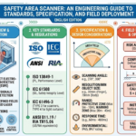
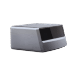
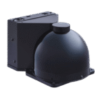
If your presence detection application is in a dangerous zone, the safety laser scanner and safety relay module combination offers convenient zone protection with user adjustable field shape.
How to Select the Right Safety Relay Module — Decision Framework
Choosing the safety relay module is systematic, not guesswork. Use these six steps to select the best fit module for your application.
- Define safety function – state what the relay has to do: monitored E-stop circuit, monitored safety gate, light curtain evaluation, two-hand control, monitored speed. Dedicated safety relay products are available for each.
- Select PL/SIL. The risk assessment (per, ISO 12100 ISO 13849-1) indicates which Performance Level is needed. Most industrial E-stop circuits are d or e.
- Choose single or dual channel. single-channel (Category 1-2) is suitable in low-risk situations. dual-channel (Category 3-4) should be specified where a wiring error under certain conditions must not disable the safety function.
- Determine number of output contacts. How many safety output contacts (N/O pair) will be needed? Standard modules come with 2-3 N/O safety output pairs. Where multiple contactors must be controlled independently, consider expansion relay modules.
- Match the supply voltage and terminal type. Ensure 24V DC or AC/DC universal voltage is specified. Decide between screw or push-in terminals, in accordance with your panel wiring practices and conductor thickness.
- Set resets and feedback options. Manual reset is normal, auto-restart is not seen. Feedback loop monitoring (external contactor mirror contact) is mandatory with Category 3/4 circuits.
📐 Quick Decision Guide
| Machine Complexity | Recommended Module Type |
| Single press + 1 E-stop | 1 basic E-stop safety relay ($80–120) |
| CNC with E-stop + door + light curtain | 3 dedicated safety relays ($300–500 total) |
| Packaging line, 6 zones, 8 E-stops | Configurable safety controller ($400–700) |
| Robotic cell, 20+ interlocks, sequential logic | Safety PLC ($2,500–5,000+) |
Example: A food processing line has 6 safety zones with 8 emergency stops, 4 safety gates, and 2 light curtains across its length. Using individual safety relays, the control panel would require 14 modules costing approximately $7000, and require complex wiring and multiple diagnostics. One simple, flexible, and low-cost safety controller with 600 dollar price tag manages all 14 tasks, wiring is simplified, diagnostics are consolidated – clearly time to switch away from the traditional approach.
For standard E-stop, safety gate, or light curtain commands to 1-3 devices; visit our safety relay module selection section to see models rated to your voltage, channel, and output configurations.
Tip: when planning to pay for a safety system, remember to include the wiring time, commissioning time and ongoing validation time into the cost equation. A 200 dollar safety relay with 2 hours wiring can be less costly in the long run than a $600 controller with an hour’s more programming or vice versa depending on the number of safety functions.
Frequently Asked Questions
What is the typical lifespan of a safety relay module?
View answer
Most electromechanical safety relay modules are rated for 100,000 to 1,000,000 mechanical switching operations depending on the contact load. At typical industrial usage rates of 20–50 cycles per day, this translates to 10–20 years of service. However, proof testing intervals defined in IEC 61508 may require functional verification every 1–5 years regardless of cycle count.
Can a safety relay module be reset automatically?
View answer
Yes, but only in limited circumstances. Most safety relay modules offer both manual and automatic reset modes, selectable via terminal wiring (bridging Y1 to Y2 for auto-restart). Auto-reset is only acceptable when the risk assessment confirms that automatic resumption does not create additional hazard — such as unmanned process equipment behind physical barriers. For any manned workstation, manual reset is mandatory per ISO 13849-1 Annex I guidance to ensure an operator confirms the hazard zone is clear before restarting.
What does Cat 4 / PL e mean on a safety relay datasheet?
View answer
Category 4 (Cat 4) describes the hardware architecture: dual-channel redundancy where accumulation of undetected faults does not lead to loss of the safety function. PL e (Performance Level e) indicates the highest level of risk reduction under ISO 13849-1, corresponding to a probability of dangerous failure per hour (PFHd) below 10⁻⁷. Together, Cat 4 / PL e means the relay module provides the highest standard safety rating for machine safety applications, equivalent to SIL 3 under IEC 62061. This rating applies to the module itself — achieving Cat 4 / PL e at the system level also requires proper wiring, qualified input devices, and correct feedback loop configuration.
Are safety relays still required if my machine has a safety PLC?
View answer
Not necessarily. A safety PLC can replace individual safety relays because it performs the same monitoring and switching functions via certified safety I/O modules. However, many installations use both: the safety PLC handles complex logic and zone management, while individual safety relays handle isolated functions on peripheral equipment that does not connect to the PLC network.
View answer
Multiple E-stop buttons can be wired in series on a single safety relay channel — any button opening the circuit triggers the stop. Practically, 5–6 buttons per channel is a common limit before voltage drop on 24V DC circuits becomes a concern, especially with longer cable runs exceeding 50 meters total.
What causes a safety relay to fail to reset?
View answer
The most common causes are: (1) an input channel still open — check that all E-stop buttons are fully released and rotated to the run position; (2) feedback loop not closed — the external contactor’s auxiliary NC contact is not confirming dropout, often because the contactor itself is mechanically stuck; (3) channel discrepancy — CH1 and CH2 did not open within the 200 ms agreement window, indicating a wiring fault or failed switch contact on one channel; (4) internal fault detection — the module detected contact welding during the previous cycle. LED diagnostics on the module front panel indicate which condition is blocking reset.
Need a Safety Relay Module for Your Application?
Browse E-stop, light curtain and safety gate units – Cat 4 / PL e / SIL 3 rated for 24V DC input, DIN rail mounting.
About This Analysis
This webpage was developed by CCH Shanghai Sensing Intelligence Technology; a manufacturer of industrial safety sensors including safety relay modules. The technical content gives information on K1/K2 redundant contacts, ISO 13849 categories of compliance, and wiring tips in accordance with IEC and ISO standards. All performance figures refer to published industry standards. Product recommendations are provided as general guidance only.
References & Sources
- IEC 61508 Electrical/Electronic/Programmable Electronic safety related systems. International Electrotechnical Commission. webstore.iec.ch
- Standards related to safety and reliability of machinery include: ISO 13849-1:2023 – Safety of Machinery: Safety-Related Parts of Control Systems. ISO. iso.org
- IEC 62061 – Safety of Machinery: Functional Safety of Safety-Related Control Systems.IEC. webstore.iec.ch.
- ISO 12100 — Safety of Machinery: Risk Assessment. ISO. iso.org.
- OSHA Machine Guarding Standard 1910.212. U.S. Department of Labor. osha.gov.
- Dahlen, A. “Introduction to the Industrial Safety Relay.” DigiKey TechForum. forum.digikey.com.
- 61508 Association. “Functional Safety Basics.” 61508.org.
- ABB. “Functional Safety and Reliability Data.” Application Note, April 2024. library.e.abb.com.
Related Articles
Reviewed by the CCH Sensing engineering team – 20+ years in industrial safety sensor design and manufacturing.