Get in touch with QJKH Company
Industrial Robot Safety Laser Scanner Applications: Welding, Polishing, Arms, and Cobots
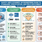
Quick Specs: Application-Ready Safety Laser Scanner (QJKH SH27)
- Scanning angle: 276° · Angular resolution: 0.1°
- Protective field radius: 3 m or 5 m @ 1.8% reflectivity Alarm zone up to 20 m
- Response time: 100 ms (configurable) Object resolution: 70 mm at ma× radius
- Certifications: IEC 61496 Type 3 · SIL 2 (IEC 61508) · PL d / Cat. 3 (ISO 13849-1)
- Environment: IP65 Ambient light immunity 3000 lu× 10 to +50 C
- Zone library: 64 static groups, 256 dynamic zones, <50 ms switching
If you already know you need an industrial robot safety laser scanner in your robot cell, the other hard question is where to mount it, how to shape the zones, and which interferer will trip it first. This guide covers four cell types – arc welding, polishing, industrial robot arms, and co-bots – with mounting geometry, zone math, and commissioning steps drawn from ISO 10218-2:2025, ISO/TS 15066, and the QJKH SH27 safety laser scanner datasheet. For the other hard question of standards, ratings, and model selection, see our companion guide on industrial safety laser scanner standards and selection.
Why Industrial Robot Cells Need Safety Laser Scanners
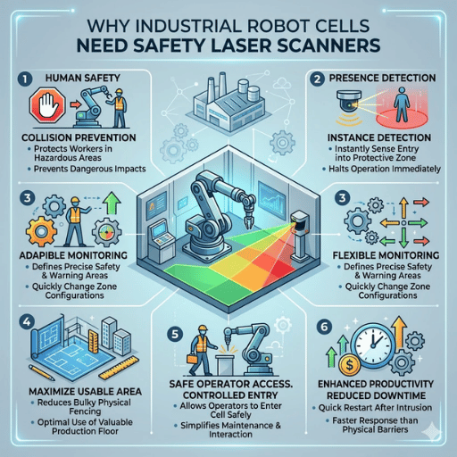
A safety laser scanner in a robot cell performs a safety function that neither fixed fencing nor light curtains can provide: it projects a configurable two-dimensional protection zone across hazardous areas on the cell floor, detects a person or object entering those hazardous zones, and sends an OSSD stop signal to the robot controller within its response time. Fixed fences block access but also block the operator every time a pallet needs to move. Light curtains guard linear openings with sub-millisecond response but can not monitor the interior of a cell.
ISO 10218-2:2025 – the revised industrial robot integration standard – now requires risk assessment to cover the entire safeguarded area, not just the robot’s mechanical envelope. Automate.org’s 2025 FAQ on the revision is explicit that workpiece geometry, tool path, programmed behavior, and payload extension must be taken into consideration. A safety laser scanner is the most flexible sensor for that job because its protection and warning zones can be taught to match an irregular reach envelope. If you are choosing between scanner technologies and certifications, our overview of industrial safety laser scanner standards covers Type 2 versus Type 3, SIL levels, and environmental ratings in detail.
All four application sections below assume you have already made a decision: you have selected a Type 3 / SIL 2 / PL d scanner such as the QJKH SH27. The question now is where to deploy it.
Welding Robot Cells: Arc Light, Spatter, and Ambient Interference
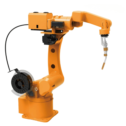
A safety laser scanner for welding robot cells has to endure three conditions at once: the intense broadband light from the arc, ballistic weld spatter, and the high ambient temperature within two meters of the torch. Each one damages a different component of the scanner.
Arc emission peaks in the UV and visible bands — approximately 200 to 550 nm — and this is why welding imaging systems documented in the AWS Welding Digest 2025 handheld laser welding safety report, use 808 to 976 nm illumination lasers in order to “outshine” the arc in that band. QJKH’s SH27 uses a 905 nm Class 1 laser for the same reason: the measurement wavelength is in a band in which the arc is not the source of significantly more photon flux than the background, and narrowband optical filters in front of the receiver block practically everything else. A published 3000 lux ambient light immunity figure is effective only for broad-band ambient illumination; narrowband interference at 905 nm is many times less. In practice this is why welding cells with Type 3 scanners certified for 3000 lux or greater very rarely falsely trip on arc light alone.
“The primary source of failure in welding cells is not optical interference – it is mechanical. Spatter accumulates on the scanner window within days if it is mounted facing the arc, turning each drop into a permanent scattering site. Mount the scanner behind the operator approach path, not in front of the torch.”
Can arc welding light blind a safety laser scanner?
Not at 905 nm with a Type 3 certified scanner, in most cell geometries. The IEC 61496 Type 3 certification procedure tests immunity to modulated light sources and ambient interference as part of qualification. Two caveats: first, the test assumes the arc is not in the direct scanning plane – aim the scanner across the operator approach path rather than at the torch. Second, spatter contamination on the optical window reduces signal margin, and a contaminated window is far more likely to falsely trip in bright ambient than a clean one. On the SH27, the window contamination indicator lamp alerts you to this before detection degrades.
Engineering Tip: position the SH27 150 to 300 mm off the floor with its 276 scanning plane parallel to the floor. Offset the unit at least 1.5 m horizontally from the torch center line, and position the primary scanning arc toward the operator door – never toward the arc. With 0.1 angular resolution, a 1.5 m standoff yields ~2.6 mm of lateral resolution per ray, sufficiently precise for a 70 mm object detection threshold.
Polishing Robot Cells: Dust, Abrasive Media, and Window Contamination
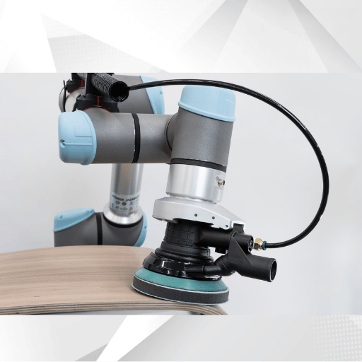
A polishing robot safety lidar performs differently from a welding scanner. Here the risk comes not from a high intensity event, but from continuous fine particulate – metallic dust from stainless, aluminum, or mild steel polishing – settling on every horizontal surface in the cell, including the scanner’s optical window. Every micron of buildup shifts the background return, and eventually crosses the detection threshold. For a detailed discussion of the SIL 2 and PL d safety integrity levels that polishing cells often require, see our standards guide.
These three design decisions will keep a polishing cell scanner operating between scheduled maintenance intervals: Tilt the scanner housing downward 10° to 15° so that it deposits dust onto the upper housing surface rather than onto the scanning window; position the polishing cell scanner downstream of, rather than upstream of, the dust extraction hood flow path so that the forward-end load on the window has been depleted; and monitor the window contamination indicator on the SH27 as a predictive maintenance signal that signals the scanner to begin rejecting valid returns, not just the laser light, thereby alerting the line operator to clean the window during the next idle cycle versus waiting until a production halt.
How often should you clean a safety laser scanner in a polishing cell?
Whatever the interval is; it has nothing to do with time or count. It depends on cell enclosure, extraction (air movement), and workpiece material. Very large, heavy stainless steel buff cells with poor extraction run end of shift window wipeowns, while lighter aluminum deburring cells with good downdraft run clear a week.
Use compressed dry air and a lint-free optical cloth; never clean with solvent-based wipes—this destroys the window’s water-repellant coating, H2O and grit adhere more quickly the next time. According to field technicians on machinists safety e-forums, dry air rather than solvent wipe extended relative interval by two or more.
Engineering Note: the specification for object resolution for the SH27 is 70mm at maximum protecting radius. All airborne particulate matter is three to four orders of magnitude smaller than this distance and does not in itself produce trips – the mode of failure is series deposition on the window, not individual particles in the beam, hence why window contamination detection is more interesting that particulate matter levels.
Industrial Robot Arm Area Safety: Reach Envelope and Zone Geometry
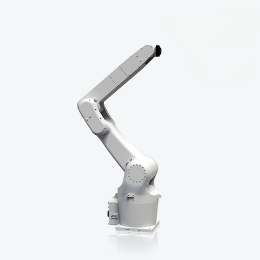
Industrial robot arm area safety starts with a geometry problem that many integrators get wrong on the first pass. Your protection zone is not bounded by where the robot base sits — it is bounded by where the robot’s tool and payload can reach during any programmed motion, plus the distance the robot travels after a stop signal. ISO 10218-2:2025 requires the safeguarded space to extend beyond this combined envelope, and the 2025 update explicitly calls out that workpiece and tool geometry are part of the envelope, not separate from it.
How do you calculate the safeguarded area for an industrial robot arm?
Represents use the RIA 15.06 / ISO 13855 minimum safety distance formula as a base then layer over your reach envelop: Momepi Sze4.
Here: D s = K ( T s + T c + T r) + D / pf
- K = 1600 mm/sec. The standard human approach velocity per ISO 13855 ( using 2000 mm/sec for a worst case allowance)
- Ts = robot stopping time after the signal, usually is between 100 to 500 ms depending on payload and configuration
- Tc = safety controller response (10 to 50 ms)
- Tr = scanner response time (100 ms for the SH27)
- Dpf = penetration distance factor, (up to 200 mm for horizontal 2D scanners (ISO 13855))
Worked example: a 20 kg-payload robot with a measured 350 ms stopping time, a 20 ms safety PLC, the SH27’s 100 ms response, and a 160 mm penetration factor yields Ds = 1600 × 0.470 + 160 = 912 mm. The scanner’s protection zone boundary must sit at least 912 mm outside the robot’s maximum reach envelope, not outside its base. IEC 61496 Type 3 certification governs the Tr term, which is why Type 3 scanners with tested response times are the correct class for robot cells. Common practice adds an additional 500 mm buffer from maximum reach to first detection zone edge — a margin that accounts for robot brake wear over service life.
SH27 hardware supports 64 static zone groups, which is typically enough to match an irregular reach envelope with a polygonal shape, rather than a rectangular approximation. Each static group can associate a warning zone (robot side acceleration/decceleration control) with a protection zone (robot stops). Its 256 dynamic zones deal with tool-change situations where the reach envelope itself shifts between programs. Types switching delay is less than 50ms, small enough to stay inside the Tc budget in the formula above.
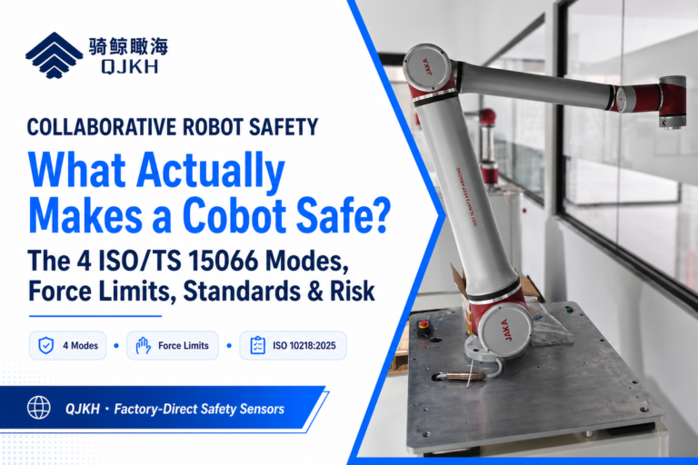
Collaborative Robot Cells: Speed-and-Separation Monitoring
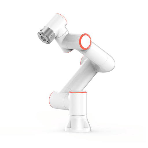
A safety laser scanner for cobot cells has a very different purpose. Under ISO/TS 15066:2016, there are four collaboration modes – safety-rated monitored stop, hand guiding, power and force limiting, and speed-and-separation monitoring (SSM). In SSM the scanner is the primary sensor. If your cobot lives on an AGV or AMR trolley, the same scanner may also be used for navigation obstacle avoidance, and our guide to mobile robot positioning lidar for AGV and AMR covers that dual-role integration.
What is speed-and-separation monitoring in ISO/TS 15066?
Speed-and-separation monitoring keeps a minimum protective separation distance — written Sp(t₀) — between the operator and the robot at all times. If that distance drops below the calculated threshold, the robot must slow or stop. The NIST and PMC-hosted analysis of SSM expresses the formula as:
Sp(t₀) ≥ ∫vH + ∫vR + ∫vS + (C + ZR + ZS)
The integrals span the sensor response time TR plus robot stopping time TS. In plain terms: operator velocity vH (default 1600 mm/s per ISO 13855), robot velocity vR, robot stopping velocity vS, intrusion margin C, and two uncertainty terms ZR and ZS for robot and operator position measurement. Sensor response time feeds into TR, so a 100 ms scanner reduces the integrated human and robot approach contributions compared with a 200 ms device. A practitioner thread on the robotiq discussion forum notes that in most real cobot cells, the robot stopping term dominates — a faster scanner cannot compensate for a slow robot brake.
With sub-50 ms zone switching, the SH27 shrinks its protection zone as the robot decelerates, which is the profitable aspect of SSM: you end up with a bigger operational workspace when the robot is moving at low speed, and the zone expands only when the robot drives at higher velocity. This is what selecting the right safety laser scanner ultimately comes down to for cobot applications: dynamic zone count, switching latency, and response time must all fit inside your Sp budget with room for robot brake wear.
Mounting and Commissioning Checklist
All safety laser scanner installation steps are the same: ignore any one at your peril, since a risk assessment auditor will identify the missing link.
- Install the safety laser scanner so the centerline is 150 to 300 mm above the final floor for horizontal floor-scan. Mounting it lower results in a crawl-zone gap; mounting it higher results in a trip-zone gap under the scanning plane.
- Level the scanning plane to within 0.5 of the reference floor. Tilt greater than 1 over a 5 m protection radius translates to ~87 mm of vertical drift at the zone boundary.
- Program the reference contour. In practice, the single biggest commissioning error is skipping this step—without a reference contour, the scanner cannot differentiate the installed environment from a new intrusion and either false-trips or fails to detect the intrusion.
- Program zone geometry as polygonal contours that match the reach envelope plus Ds. Rectangles that leave dead space on one side and not enough margin on the other compromise the zone.
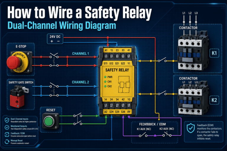
- Connect OSSD outputs to a Type 3 / Cat. 3 safety relay module for OSSD integration. Wiring directly into a non-safety-rated PLC voids the PL d rating for the entire safety function.
- Integrate E-stop and reset functions. Per RIA 15.06, automatic rearm after a protective stop is prohibited—manual reset outside the protection zone is mandatory prior to resuming motion.
- Check stop category against the risk assessment. The distinction between Category 0 (immediate power-down) versus Category 1 (controlled stop plus power-down) influences Ts in the distance formula.
- Conduct the 70 mm test object run. Traverse an opaque 70 mm diameter cylinder around the zone perimeter at 1600 mm/sec and verify the robot comes to a stop before the object reaches the hazard.
- Arrange for a yearly recalibration. Reference contour teach should be re-done annually and following a cell geometry modification.
Often done incorrectly: Commissioning the safety laser scanner before you have finished robot stopping-time measurement. The stopping time measured in teach mode (robot limited to 250 mm/sec) is not the stopping time when operating automatically – you must re-run at operating speed with payload installed before calculating zone size.
SH27 Configuration Guide per Application
The four-application configuration matrix below takes each of the four types of robot cells identified above and matches it to the typical SH27 model, zone mode, and maintenance interval it each could most frequently use. This is merely a starting point, not a substitute for a risk assessment. For the full standards matrix and selection guide, see the companion article.
| Application | SH27 model | Protective radius | Zone mode | Window maint. |
|---|---|---|---|---|
| Welding cell | SH27-05D | 5 m | PAA (protection + dual pre-warn) | Weekly |
| Polishing cell | SH27-05D | 5 m | PAA | End of shift |
| Stationary robot arm | SH27-03D or -05D | 3 – 5 m | PP (dual protection zones) | Monthly |
| Cobot SSM | SH27-03D (Ethernet) | 3 m | PAA + dynamic zone switching | Monthly |
All SH27 models are certified to IEC 61496 Type 3, SIL 2 per IEC 61508, and Cat. 3 / PL d per ISO 13849-1:2023. Only the -03D / -05D Ethernet variants support the dynamic zone switching needed for cobot speed-and-separation monitoring; the -S variants are sufficient for stationary welding, polishing, and fixed arm cells. CCH Shanghai’s 20+ years of safety sensing R&D includes OEM customizations – zone count, output type, and enclosure variants – for large integrations.
Get a free SH27 sample and application consultation from our QJKH SH27 safety laser scanner product page. For speed-and-separation monitoring of a mobile platform, pair the SH27 to a navigation-class YB27 industrial lidar sensor; when guarding a point-of-operation inside the cell, a point-of-operation safety light curtain is usually the faster choice.
Frequently Asked Questions
How do safety laser scanners work with industrial robots?
Answer
SH27 safety laser scanners rotate a 905 nm Class 1 laser to measure time-of-flight reflections around a 270 to 276 degree arc at 25 Hz or faster; powered by a 24 VDC supply, they must also be wired into the robot controller using the safety-rated Safety Control Unit to implement the stop response. Upon protection zone entry, the OSSD outputs switch off and stop the robot.
How are safety laser scanners different from light curtains?
Answer
Light curtains guard linear openings with sub-millisecond response; safety laser scanners provide configurable two-dimensional zones with 60 to 120 ms response. Curtains are the right choice at gates and conveyor openings; scanners are the right choice inside the robot cell where the protection zone is irregular.
Can a safety laser scanner detect weld spatter or polishing dust as an object?
Answer
No – airborne dust particles are three to four orders of magnitude smaller than the 70 mm minimum object resolution and will not trigger the protection zone alone. Instead, the failure mode is accumulation on the optical window, which is why cells in dusty environments should have a window contamination indicator and a scheduled cleaning interval, not increased sensitivity.
What response time do I need for a cobot safety scanner?
Answer
100 ms is a practical goal for most Zogirem frequency and speed control cells. Faster scanners have lower the effective TR term in the protective separation formula, but robot stopping time is usually dominant so determine your TS before paying for a faster scanner.
Do I still need a safety fence if I install a safety laser scanner?
Answer
Often – particularly when ejected parts or chips are thrown by the robot arm, or the machine runs at high payload. A scanner only detects presence, not containment, so your risk assessment decides whether a fence alone, fence plus scanner, or scanner-only approach satisfies your risk profile.
How many warning and protection zones can one scanner manage?
Answer
The QJKH SH27 supports 64 static zone groups and 256 dynamic zones, with zone switching under 50 ms. For most robot cells, 8 to 16 zones accommodate the various robot programs and performance parameters experienced during normal operation.
Transparency Note
All QJKH SH27 specifications in this article – scanning angle, response time, certification ratings, zone library sizes – are sourced from CCH Shanghai’s official product datasheet (catalog V2026-1-30). Safety standards reference values for response times and clearances cited below may not exactly match the real working parameters of your cell, due to payload and brake condition effects – verify measured values during installation.
References & Sources
- ISO 10218-2:2025 — Robotics: Safety requirements for robot integration — International Organization for Standardization
- ISO/TS 15066:2016 — Collaborative robot safety technical specification — International Organization for Standardization
- Implementing Speed and Separation Monitoring in Collaborative Robot Workcells — U.S. National Library of Medicine / PMC
- OSHA Technical Manual Section IV, Chapter 4 — Industrial Robots — U.S. Department of Labor
- Updated ISO 10218 FAQ — Association for Advancing Automation
- Providing a Safe Environment for Handheld Laser Welding — American Welding Society
Related Articles
- Industrial Safety Laser Scanners: Standards, Ratings, and Selection Guide
- Positioning LiDAR for AGV and AMR Navigation
- Collaborative Robot Risk Assessment Walkthrough (coming soon)
- Safety Relay Module Integration for OSSD Outputs (coming soon)