Get in touch with QJKH Company
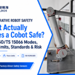
Obstacle Avoidance LiDAR for Mobile Robots: The 3-Sensor Stack Your AGV Actually Needs
A 2026 engineer’s guide to the three LiDAR categories every AGV, UAV, and cobot integrator conflates – obstacle avoidance, SLAM navigation, and IEC 61496 safety scanning – and why a correctly specified mobile robot usually carries two or three of them, not one.
Quick Specs — Obstacle Avoidance LiDAR at a Glance
- Typical response time: 67 ms (2-scan) to 536 ms (16-scan), default 67 ms
- Scan field: 270° horizontal, 0.3° adaptive angular step
- Detection range: 15 m to 40 m at 70% reflectivity
- Zone logic: 16 user-drawn zone groups, switched by 4 e×ternal inputs
- PNP/NPN dual-channel (warning + stop), optional Ethernet UDP point cloud
- Ambient light immunity: 100,000 lu× (outdoor capable)
- IP rating / power: IP65 / < 3 W at 9-28 VDC
- Safety rating: Not IEC 61496 certified – not a substitute for a safety laser scanner
Values reflect the QJKH YB27 series (2026 product manual) as a representative 2D obstacle-avoidance LiDAR. Other vendors publish similar ranges; check the model-specific datasheet before design lock.
An obstacle avoidance lidar sensor is the lidar technology that stops your mobile robot before it hits something – a protective layer that lets the machine avoid obstacles in real time in the complex environments where AGVs, cobots, and drones actually work. It is not the sensor that tells the robot where it is on a map, and it is not the device that makes a collaborative cell legally safe under ISO 10218-2. Those are three different jobs done by three different classes of LiDAR, and most AGV and cobot field problems begin with someone picking one sensor and assuming it covers all three.
This guide walks through the distinction in the language a design engineer actually uses: response time, protective field geometry, zone switching, output interface, and certification class. It names concrete SKUs where it helps, cites the standards that govern the safety boundary, and ends with a 3-tier sensor stack recommendation you can drop into a specification document.
What Is an Obstacle Avoidance LiDAR Sensor?
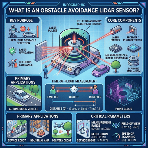
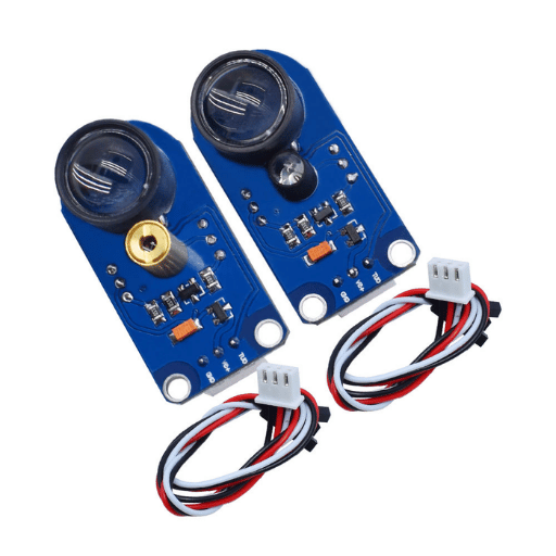
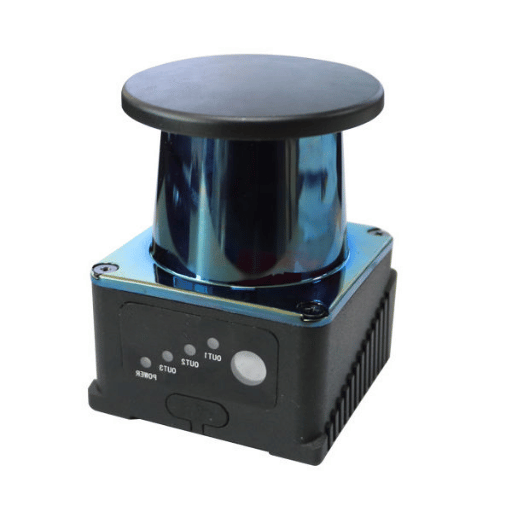
An obstacle avoidance LiDAR sensor is a light detection and ranging device that watches one or more user-defined zones in front of a moving machine and sends a digital stop or slowdown signal the instant something enters a zone. It is optimised for reaction speed and zone geometry, not for point-cloud density or functional safety certification. The hardware overlaps with other LiDAR classes – the same optical engine often appears in all three – but the firmware, the output interface, and the certification boundary separate them completely.
Three categories of 2D LiDAR show up in mobile-robot specifications, and confusing them is the single most common specification error in AGV integration. The distinction is worth stating once, flatly:
| Category | Primary Job | Output | Certification | Representative SKU |
|---|---|---|---|---|
| Obstacle avoidance LiDAR | Stop the robot before collision | PNP/NPN digital (warning + stop) | Not safety-rated (EN 60825-1 laser class only) | YB27-25HS (25 m, 0.3°, 16 zones) |
| Positioning / navigation LiDAR | Build a map and localise in it (SLAM) | Ethernet UDP point cloud | Not safety-rated | YB27-25HE (0.1° resolution, 25 Hz) |
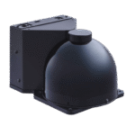
| Safety laser scanner | Legally participate in the safety function | OSSD dual channel (type-rated) | IEC 61496 Type 3, SIL 2, PL d | SH27 (pair with an OSSD-compatible relay) |
If your design task is “know where the robot is”, you want a positioning LiDAR — our companion guide to positioning LiDAR for AGV and AMR platforms covers point-cloud density, SLAM feature extraction, and why 0.1° angular resolution matters for map quality. If your task is “make this cell legally safe for a human to work in”, you want an industrial safety laser scanner certified to IEC 61496 Type 3. This article covers the middle category — the sensor that actually throws the stop.
“The most frequent field implementation challenge we see with AGV integrators is that the obstacle-avoidance LiDAR is defined in the safety risk assessment as the safety device. It is not. Per IEC 61496 and ISO 10218-2, an uncertified sensor cannot reduce the safety function – regardless of how quickly it appears on paper.”
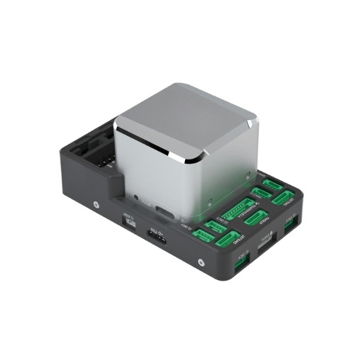
Engineering Note. The YB27-25HS (obstacle avoidance variant) and YB27-25HE (navigation variant) share the same optical bench and dToF core. They differ only in firmware and output board: the HS exposes a PNP/NPN zone-violation signal with 16 configurable zone groups; the HE exposes an Ethernet UDP point cloud at 0.1° angular resolution. The dual-output YB27-25HD carries both boards in one housing. This hardware reuse is why engineers assume “one LiDAR does everything” — and it is also why the firmware is where the job actually lives.
SLAM navigation and obstacle avoidance are not competing options; they are complementary layers. A navigation LiDAR enables the robot to know its location on a map. An obstacle avoidance LiDAR enables the robot to respond to objects that are not in the map — a pallet left in an aisle, a worker standing on the robot’s path, another AGV mid-way through a task transition. A well-built AGV runs both layers in parallel, because neither one does the other one’s job.
The design parameters diverge radically once you look past the common hardware:
| Priority | Navigation LiDAR cares about | Obstacle avoidance LiDAR cares about |
|---|---|---|
| Top priority | Angular resolution (0.1°) for SLAM features | Response time (67 ms) and zone-switch latency |
| Second | Point-cloud density and update rate | False-alarm rate on low-reflectivity targets |
| Third | Detection range for loop closure | Zone-shape flexibility (number of groups) |
| Interface | Ethernet UDP to the SLAM stack | PNP/NPN hardwired to the motion controller |
The underlying dToF ranging principle is identical and we do not re-derive it here; our positioning LiDAR deep dive covers the physics and the point-cloud density trade-offs in depth. What is relevant to this discussion is the data path. A navigation LiDAR streams raw scans to a host that runs SLAM and path planning, then the host decides what to do. An obstacle avoidance LiDAR closes that loop on-sensor — it decides zone violated or not violated inside its own MCU, drives a PNP output, and the host never touches the point cloud.
Yes — dual-output sensors exist and they are a legitimate choice for single-sensor AGV platforms that do not require certified safety. The YB27-xxHD family (15HD, 25HD, 35HD, 40HD) carries an Ethernet UDP point cloud and a PNP zone output on the same housing, fed by one optical engine. One device handles both the SLAM job and the zone-stop job. The caveat is honest: a dual-output sensor still is not safety-rated. If your application is a non-certified indoor AGV, the YB27-25HD can replace two sensors and save a cable run. If your application is a cobot cell or a mixed-traffic warehouse where people will be near moving machinery, you still need a separate safety scanner running in parallel.
Common mistake — the “soft zone” trap. Integrators who already have a navigation LiDAR sometimes try to avoid the second sensor by implementing zone detection in host software: the SLAM stack reads the point cloud, looks for points inside a software-defined polygon, and commands a stop over the fieldbus. This adds anywhere from 80 ms to 150 ms of software latency on top of the sensor scan time, and that latency is not deterministic — it varies with host CPU load. A hardware zone output on the sensor avoids the whole software path and is bounded by the scan period alone. On an AGV moving at 1.2 m/s, the difference between a 67 ms hardware stop and a 200 ms software stop is roughly 16 cm of travel — often the difference between a nudge and a pallet collision.
AGV and UAV Obstacle Avoidance LiDAR: Payload, Range, and Environment
The secondary keyword agv and uav obstacle avoidance lidar conceals a real engineering disagreement. Vehicles on the ground and in the air are asking somewhat different questions of the same family of sensors, and the benchmarks crossover only at the middle. Listing both requirements side-by-side on one spec sheet allows integrators to see why any “one LiDAR to rule them all” solution is almost sure to fail for one platform or the other.
| Requirement | AGV / AMR | UAV / drone |
|---|---|---|
| Detection range | 25 m to 40 m (warehouse aisle + deceleration buffer) | 15 m to 25 m per sensor, 360° coverage via 4-6 units |
| Zone management | 16 zone groups (different aisles, different speeds) | Fewer, altitude-adaptive; speed-of-flight modulation |
| Output interface | PNP/NPN to a PLC or AGV controller | Serial/UART/CAN to a lightweight flight controller |
| IP / environment | IP65, -10 to +50 °C, 10 g shock, vibration 10-55 Hz | Weight critical (<300 g), wind/dust tolerance, outdoor light |
| Power budget | Generous (onboard DC bus, 9-28 V) | Tight — <3 W sustained is a sub-1 kg drone ceiling |
| Ambient light immunity | Indoor bright (20 k lux) plus dock/yard transitions | Outdoor direct sun (up to 100 k lux) |
Engineering Note-the 100,000 lux ceiling. Ambient light immunity is the single spec most often overlooked in datasheets. A LiDAR with 40,000 lux immunity is perfect inside a warehouse but will flood-saturate on a loading dock at noon.
The YB27 series is up to 100,000 lux–about three times the throughput spec sheet of equivalents SICK NAV3xx navigation LiDARs–which explains why it’s found in outdoor-transitioning AGV designs and fixed-wing UAV obstacle detection. The number matters because the standard autosampling cycle on a lower-immunity sensor is to report missed returns as no obstacle, which is the worst possible failure mode.
Benewake, in its own notes on robot obstacle avoidance, states that “black or low-reflectance objects absorb light very strongly, reflecting very little light back to the sensor”, so that sensor may often misdetect such obstacles or not pick them up at all. Here this is why datasheets state range at a certain reflectivity (for YB27 usually 70% – the YB27 spec) and publish a second figure at a lower reflectivity (commonly 10% – about 1/3 to 1/2 of the stated range). When under specifying for an outdoor AGV experiencing black rubber bumpers on forklifts, expect that second specification figure to matter.
Scenario – a factory retrofit in Ningbo. An automated warehouse operator converted 40 tuggers from fixed-path induction guidance to dynamic SLAM navigation. The integrator wished to run one sensor rather than two per tugger, so settled on the YB27-25HD dual-output variant: our Ethernet UDP output fed the on-vehicle SLAM stack, our PNP zone output fed a hardwire stop chain. Sixteen zone groups were fast-switching bi-directionally to the different aisles, driven by four external inputs ready-state on entering each new zone. Response time on the stop path was kept bounded at the 67 ms hardware limit – the latency of the SLAM software no longer read the safety-critical path at all. No cobot cells were involved so no IEC 61496 rated scanner was demanded; the design hit its goal without consulting the safety-cert’d tier.
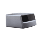
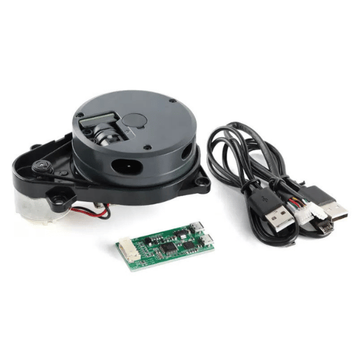
For UAV obstacle avoidance, sensor fusion is the dominant pattern. Research synthesised across recent academic literature on autonomous aerial obstacle avoidance reports accuracy figures above 94% only when LiDAR is fused with IMU, camera, and in some cases MIMO radar inputs — never on a single sensor alone. A bare 2D LiDAR on a drone is a supplement to the vision stack, not a replacement for it. That is why UAV platforms tend to specify several small sensors with modest individual range rather than one long-range unit, and why the power-and-weight budget usually dominates range as the limiting constraint. Browse the YB27 obstacle-avoidance LiDAR range to see how the 52×52×70 mm housing and <3 W power draw fit into both AGV and UAV envelopes.
Collaborative Robots and Cobot Cells: The Safety-Rated Boundary
The secondary keywords lidar sensor for collaborative robot and lidar sensor for cobot safety invite an answer that is flatly wrong if given casually. An obstacle avoidance LiDAR cannot, on its own, satisfy the safety requirements of a collaborative robot cell. It can support them; it cannot close them. The reason is a single clause in Part 2 of the IEC 61496 standard on electro-sensitive protective equipment: a safety function with a required performance level of PL d (or SIL 2) must be implemented with a Type 3 ESPE. An obstacle avoidance LiDAR without Type 3 certification is, by definition, not a Type 3 ESPE.
Honest disclosure — the compliance trap. The parameters in an obstacle avoidance LiDAR datasheet look more than good enough on paper to stop a robot. The response time is faster than some certified scanners; the zone logic is more flexible; the price is lower. None of that matters to a risk assessment. ISO 10218-2:2025 — which now incorporates the former ISO/TS 15066 guidance on power-and-force-limited cobot operation — requires the device used in the safety function to be certified to the relevant Type. If the device is not certified, the integrator carries the liability personally, and the cell will not pass a notified-body audit. That is not a theoretical concern — it is the single most common reason cobot retrofits fail integrator-level sign-off.
The proper arrangement is a double sensor cell, and the logic is clear once you have seen it put down on paper:
- Primary safety device — a Type 3 safety laser scanner. This is the device that talks to the robot’s safety-rated stop input, typically over an OSSD dual-channel output or a fieldbus with a safety protocol. It is the device the risk assessment names. Our industrial safety laser scanner guide walks through the Type 3 boundary in detail, including the treatment of why Table 2 of IEC 61496 maps PL d directly onto Type 3.
- Secondary avoidance device — an obstacle avoidance LiDAR. This is the device that implements the non-safety soft behaviours: approach-aware speed modulation, courteous slowdowns around humans, zone-based route re-planning, path-following anti-collision. These are productivity features, not safety features, and it is standard practice to do them with an uncertified LiDAR because the safety function is already closed by the scanner running in parallel.
Universal Robots’ own compliance documentation confirms this split: UR cobots comply with ISO 10218-1:2011 and the applicable portions of ISO/TS 15066, but the text is explicit that most of ISO/TS 15066 is directed at the integrator building the cell, not at the robot OEM. The integrator is the one who selects the sensor class, proves the risk reduction, and signs the CE declaration. An uncertified LiDAR in that role is a liability transfer, not a cost saving.
Engineering Note — speed-and-separation monitoring (SSM) vs power-and-force-limiting (PFL). The two collaborative modes in ISO 10218-2 place different demands on the sensor stack. SSM requires continuous surveillance of a separation distance that shrinks with robot speed — this is where a Type 3 safety scanner is mandatory because the separation monitoring function is part of the safety function. PFL, by contrast, relies on the robot’s own joint torque limits to make contact safe, and does not strictly require any external perception sensor for the safety function — though a secondary obstacle avoidance LiDAR is still common for productivity reasons. Naming which mode you are using, in the risk assessment, decides whether the obstacle avoidance LiDAR is a nice-to-have or a design-stopper. Our safety scanner guide walks through both modes with concrete distance calculations.
Is a LiDAR enough to make a cobot cell safe?
No. A LiDAR alone is not enough unless it is certified to IEC 61496 Type 3. An obstacle avoidance LiDAR, however accurate, cannot legally participate in a cobot cell’s safety function. Treat it as a secondary productivity sensor and pair it with a certified safety laser scanner on the primary safety path. The U.S. equivalent standard, ANSI/RIA R15.06-2012 as referenced in the OSHA Technical Manual, draws the same boundary.
Obstacle Detector LiDAR Beyond Mobile Robots
The search term obstacle detector lidar is not exclusive to AGVs and drones. Fixed automation uses the same sensor class for any job that looks like “watch a zone, send a stop, ignore the point cloud.” Once you recognise the pattern, the applications show up in places that do not sound like robotics at all.
- Automated parking garages. A single 270° scanner covers several parking bays with 16 independent zones switched by occupancy logic — replacing a row of individual ultrasonic bay sensors with one LiDAR at a third of the cabling cost.
- Dock-leveller anti-crush. A LiDAR mounted at the dock edge detects whether a trailer is present and whether a worker has stepped into the crush zone — faster and less maintenance-heavy than a photoelectric curtain across a 3 m gap.
- Overhead crane sway and keep-out zones. A 2D LiDAR watches the floor under the load for any violation, independent of the crane operator’s line of sight. The same zone-based pattern appears on rail-mounted power line inspection gantries, where a fixed LiDAR polls a keep-out volume around the energised conductor.
- Conveyor and loading automation. Zone-based anti-jam detection on packaging lines, replacing photoelectric trees that drift out of alignment.
The instinct in all four applications is to reach for ultrasonic first because “LiDAR is expensive.” The actual numbers push the other way once latency is in the budget. Ultrasonic echo delay at a 15 m range is roughly 90 ms one-way — nearly 200 ms round-trip — and that is before any filtering. A 2D LiDAR at the same range has a 67 ms default response and stops adding latency once the scan period is met. For zone applications where the trigger signal must be in the motion controller within 100 ms, ultrasonic is not cheaper; it is technically infeasible.
Scenario – a 3 bay parking garage in Hangzhou. A municipal small automated parking operator removed 12 individual ultrasonic bay sensors and replaced them with 3 YB27-25CS obstacle-avoidance LiDAR units, one for each bay. Each module was set up with 16 zone groups covering the ranges of vehicle-entry, vehicle-presence, worker-intrusion, and faults-clear states. Simply removing the cabling saved around 65% of the original parts bill and the common crosstalk artefacts in the ultrasonic array in adjacent bays cleaned out completely – the 270 LiDAR volume was fully isolated bay-to-bay by design. The host PLC logic was left alone, the input line just swapped out.
Key Specs for Obstacle Avoidance LiDAR: Engineering Reference
This belongs taped to the wall on top of your specification workbooks. Every row is a real value and a concrete participant with a units, not a marketing check-list adjective. The values come from the QJKH YB27 product manual 2026 series as-is; use as leverages and check that the models you will ship have their own datasheets to compare directly to.
| Parameter | Typical value | What to check on your datasheet |
|---|---|---|
| Response time (zone violation → output) | 67 ms (2-scan) to 536 ms (16-scan) | Number of scans required to confirm an obstacle |
| Zone groups and switching | 16 groups, 4 external inputs | User-drawn shapes, not fixed rectangles |
| Output interface | PNP / NPN configurable, dual-channel | Warning + stop on independent lines |
| Angular resolution (avoidance firmware) | 0.3° adaptive at 30 Hz default | Navigation firmware goes to 0.1° — different SKU |
| Scan field of view | 270° horizontal | Blind zone geometry behind the sensor housing |
| Ambient light immunity | 100,000 lux | SICK NAV3xx publishes ~40,000 lux — be explicit if outdoor |
| Detection range (at quoted reflectivity) | 15 m / 25 m / 35 m / 40 m at 70% | Ask for the 10% figure as well |
| Accuracy / repeatability | ±2 cm typical, 4 mm repeatability (1σ, 10% target) | Test conditions always stated with the number |
| Power | < 3 W no-load at 9-28 VDC | Startup inrush and heating-coil draw separately |
| Environmental | IP65, -10 to +50 °C operating | 10 g shock, 10-55 Hz vibration for mobile platforms |
| Certifications held | EN 60825-1 Class 1, EN 61326-1, UL 61010-1 | IEC 61496 not included — verify explicitly |
Engineering Note — the 67-ms Rule. The default 67 ms response time on a typical 2D obstacle avoidance LiDAR is not the whole stopping latency of the machine. The full time from obstacle entry to wheels-stopped is the sum of four terms: sensor response time, PLC scan cycle, drive controller command latency, and mechanical stopping time of the robot itself. For an AGV moving at 1.2 m/s with a 67 ms sensor, a 10 ms PLC cycle, a 20 ms drive latency, and a 300 ms mechanical stopping time, the total is 397 ms. At 1.2 m/s that is 48 cm of travel. Rule of thumb: the sensor response time should sit at or under 10% of the total stopping-time budget. If your AGV’s total budget is 500 ms, anything above 50 ms on the sensor alone starts to dominate the margin. This is the 67-ms Rule — it is where the default scan count came from, and it is why vendors publish the longer 16-scan setting (536 ms) only as a filter-aggressive fallback, never as a design target.
A paradoxical finding from industry practice: the faster sensor is often specified by integrators for slower machines. A tugger at 0.6 m/s does not need 67 ms; 200 ms is already comfortable. But specifying the fast sensor is insurance — it leaves headroom for PLC scan jitter, drive command delays, and the eventual specification creep where the customer asks to run the AGV at 1.5 m/s “just for the long aisles.” Response time that looks like overspecification on Day 1 almost never is on Day 500.
Selection Checklist and 3-Tier Sensor Stack Recommendations
The following question set is what this article was written to support. The question is not “which obstacle avoidance LiDAR should I buy?” it is “which stack of sensors fulfills the application needs, and what is the tier I am actually building to?” All three tiers accommodate B2B mobile robot applications, but choose the one that matches your off-the-shelf risk assessment.
| Tier | Application | Sensor stack | Compliance path |
|---|---|---|---|
| Tier 1 | Indoor AGV, fixed path, no human traffic in operating zone | 1× YB27-15CS or YB27-25CS (obstacle avoidance only) | Machinery directive conformity, no IEC 61496 device required |
| Tier 2 | Outdoor or long-range AGV, dynamic environment, no direct human collaboration | 1× YB27-25HD (dual-output nav + avoidance) or YB27-25HE + YB27-25CS as two devices | Still no certified device, but a two-layer architecture improves hazard coverage |
| Tier 3 | Cobot cell, mixed-traffic warehouse, any environment requiring a PL d safety function | SH27 safety laser scanner plus YB27-15CS for productivity zones — two devices, two risk layers | IEC 61496 Type 3 device on the safety path, ISO 10218-2:2025 cell integration |
12-point integrator checklist:
- Is a safety function (PLd or higher) required for this design? If so,Tier 3 is required.
- What is the top robot speed? Multiply this by total required travel time to get protective field depth.
- Is the response time budget driven by the sensor, the PLC, or the drive? If sensor > 10%, upgrade.
- Is outdoor visibility a concern? Check ambient illuminance 100,000 lux and IP65.
- Are the obstacles low reflectivity (dark floors, black rubber)? Request the 10% reflectivity range.
- How many aisles / zones / speeds? If more than 4, a single LiDAR 16 zone-group capability will be decisive.
- What fieldbus terminates the output? PNP/NPN through common hardware; Ethernet UDP through SLAM; OSSD only through the exclusive Approved Scanner.
- What is the certification boundary? Laser class (EN 60825-1) only, or defined safety PLC programming (IEC 61496)?
- Power budget – is the sensor powered through inverter bus (compatible range 9-28 VDC) or directly from a drone battery (< 3 W hard limit)?
- Temperature environment – is the sensor cold or hot? Enclosed with heated enclosure or exposed to the outdoors?
- Does the risk assessment match the sensor manufacturer? An out-of-specification mismatch is the typical reason integrators cannot pass audit.
- Is a sensor recalibration maintenance schedule planned? Up to 4 concurrent users of multi-user support (YB27) with configuration.
Ready to pick a specific SKU? Browse the full QJKH obstacle-avoidance LiDAR range for Tier 1 and Tier 2 designs. For Tier 3, pair the obstacle avoidance LiDAR with an IEC 61496 Type 3 safety laser scanner on the safety-rated path, and terminate both through an OSSD-compatible safety relay feeding the robot’s safety input.
Transparent disclosure. This article is published by QJKH (CCH Shanghai Sensing Intelligence Technology Co., Ltd.), headquartered in Hangzhou with more than twenty years of R&D in industrial safety sensing. The YB27 and SH27 parameters cited throughout are drawn from the 2026 QJKH product manual; standards citations (IEC 61496, ISO 10218-2:2025, EN 60825-1, and the OSHA ANSI/RIA R15.06-2012 reference) come from the primary sources listed below. We sell the hardware we describe, and we prefer to be explicit about it rather than hide the commercial link — the engineering distinctions above hold regardless of which vendor you end up buying from.
Frequently Asked Questions

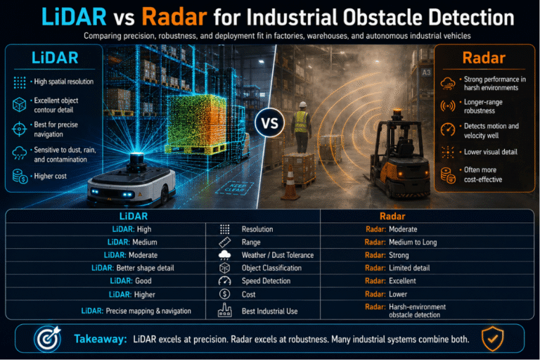
What is the main advantage of LiDAR over ultrasonic or radar for obstacle detection?
View answer
LiDAR achieve about 4mm repeatability in 1 under controlled environment than about 1cm for typical ultrasonic array; and it maintains that accuracy throughout the 270 scan field not just at a center point target in a narrow cone. Its ambient light immunity of 100,000lux is superior to photoelectric curtain outside, and unlike radar it fuses small and tightly packed objects. It’s the tradeoff that rain, fog and reflective low-reflectivity surfaces limits range, and dynamic environment sensor fusion is common in UAVs less so in an indoor environment.
How does weather affect obstacle avoidance LiDAR performance?
View answer
Heavy rain, snow & dense fog causes light scatter & attenuation, leading to potentially reduced effective detection range and increased false-positives on water droplets. Modern firmware mitigates this with multi-pulse filtering and adaptive thresholding, but physics remains physics, and you can expect effective range to reduce significantly in bad weather. For safety-critical outdoor work, combine the laser with radar or with a certified Type 3 safety laser scanner whose Type classification accounts for listed environmental conditions.
What computational requirements does real-time 2D LiDAR obstacle avoidance need?
View answer
Zero host CPU. Obstacle avoidance LiDAR sensors determine how a zone is violated internally and trigger a PNP output directly; the host just reads a digital line. Navigation LiDAR runs SLAM on the point cloud and requires edge-class computation horsepower.
Can obstacle avoidance LiDAR replace a safety laser scanner in an AGV or cobot cell?
View answer
No. Under IEC 61496 Part 2 as quoted by the German DGUV technical guidance, a safety function requiring PLd or SIL2 must implement with a Type 3 electro-sensitive protective device. ISO 10218-2:2025 (which now includes the former ISO/TS 15066 cobot guidance) requires this certified device in the safety function. A obstacle avoidance laser turret without Type 3 certification cannot participate in the safey function legally no matter how fast response time reads. Pair it with a certified safety laser scanner on the primary safety path and use the obstacle avoidance device for nonsafety productivity behaviors such as courtesy slowdowns and zone-based routing.
How many zones can a typical obstacle avoidance LiDAR monitor?
View answer
A generic 2D obstacle avoidance laser turret supports 16 user-defined zone groups, switched at run-time by four external digital inputs. Different zones for different aisles, different speeds, and different load states are configured by an helper application and stored in the sensor.
What is the typical response time for an obstacle avoidance LiDAR?
View answer
The default on an average 2D obstacle avoidance LiDAR is 67 ms – two 2ms scans confirming a obstacle before the output is driven; a 16-scan filter-aggressive setting maxes out at 536 ms. The shorter default adapts better for latency-sensitive fast-moving vehicles; the longer calibration favors false-alarm sensitivity. Decide the setting by working backwards from the total stopping time budget for the machine and leaving the sensor no more than 10% of that budget to eat.
References & Sources
- Relationship between the Type of an ESPE and the SIL/PL – German Social Accident Insurance (DGUV), Institute for Occupational Safety and Health (IFA)
- ISO 10218-2:2025 Robotics — Safety requirements for robot systems in an industrial environment — International Organization for Standardization
- OSHA Technical Manual Section IV Chapter 4: Industrial Robots and Robot System Safety – U.S. Department of Labor, Occupational Safety and Health Administration
- An Introduction to the IEC 61496 Series of Human Presence Detection Standards – Analog Devices EngineerZone Spotlight
- Updated ISO 10218 — Frequently Asked Questions — Association for Advancing Automation (A3), Robotic Industries Association (RIA)
- Autonomous Aerial Obstacle Avoidance Using LiDAR Sensor Fusion – Liang et al., 2023, PubMed Central (PMC10306222)
Related Articles
-
- Positioning LiDAR for AGV and AMR: SLAM and point-cloud navigation – the companion guide covering navigation-grade LiDAR selection.
- Industrial Safety Laser Scanners: IEC 61496 Type 3 deep dive – the certified safety device that pairs with this one on the Tier 3 stack.
Reviewed by the QJKH industrial safety sensing engineering team. QJKH (CCH Shanghai Sensing Intelligence Technology Co., Ltd.) has been active in industrial safety sensing R&D for more than twenty years, with product lines spanning obstacle avoidance LiDAR, navigation LiDAR, and IEC 61496 Type 3 safety laser scanners.