Get in touch with QJKH Company
Picking the right LiDAR for overhead crane safety is the single most consequential sensor decision a plant engineer makes after the crane itself. Pick the wrong wavelength and your system blinds out in mill dust. Under-spec the detection range and your brakes will never catch a 20-ton load in time. Choose a 2D unit where 3D is required and your stacked material becomes an invisible wall. This guide walks through the physics, the selection math, the installation sequence, and the field pitfalls we see most often, with OSHA, ASME B30.2, IEC 61496, and peer-reviewed data backing every section.
It is written for maintenance engineers, safety managers, and EPC integrators who have to specify a crane anti-collision system next week and want a guide that goes beyond brochure language. By the time you finish, you will know how to spec, install, and integrate an overhead crane LiDAR sensor without getting burned.
📐 Quick Specs — Overhead Crane LiDAR at a Glance
- Detection range runs 0.5–40 m on a 2D unit, climbing to 120 m on 3D sensors or long-range 2D such as the Hokuyo UGM-50LAP
- Field of view: 190–360° horizontal; 30–90° vertical on 3D units only
- Point density: about 1,080 points per rotation on 2D scanners, versus tens of thousands to 1.2 million points per second on 3D
- Wavelengths: 905 nm dominates 2D safety scanners; 1550 nm shows up on long-range outdoor 3D
- Refresh rate sits in the 15–40 Hz band
- Protection rating: IP65 to IP67 — outdoor and gantry installations require IP67
- Interfaces: Ethernet/IP, PROFINET, EtherCAT, or a plain dry-contact safety relay
- Certifications to look for: IEC 61496-3 Type 3 ESPE, ISO 13849-1 PL d Cat 3, SIL 2
- Installed cost per crane: US$3,500–US$18,000 covering sensor, mounting, and PLC programming
Why Overhead Cranes Need LiDAR: The Real Failure Modes
Way better to know what goes wrong before wasting a dollar on sensors. Between 2000 and 2023, a compilation of the OSHA accident search database by Hokuyo-USA yielded 156 injuries and 130 fatalities related to overhead crane accidents in the workplace—US$500-m impact in aggregate—aggregates of the database are retrievable publicly via the OSHA accident search portal, and the 2024 Census of Fatal Occupational Injuries published by the US Bureau of Labor Statistics persist with fatal work injury rates of 3.3 per 100K FTE across U.S. industries.
Those numbers become easier to act on when you break them into hazard classes that a safety sensor actually has to prevent:
- Crane-to-crane tandem collisions happen when two bridges on the same runway converge at speed, usually during hand-offs between bays. Limit switches help in one axis but miss trolley-to-trolley geometry.
- Crane-to-structure impact — end trucks run into runway stops or the building column when a worn brake lets the bridge coast past its stop point.
- Load-path obstacles — a rigger leaves a tool cart in the travel path and the swinging load catches it before the operator registers the problem.
- Crane-to-worker strikes occurs when a person walks under a moving load in a blind corner. This particular hazard class is the one that academic research has focused most effort quantifying, including the TwinFlow project at Aalto University.
One senior plant engineer on an industry forum described an incident where an overhead crane “spanned the whole building and had known-bad brakes” while the lead man was walking through the shop holding roughly US$25,000 of stock — a reminder that the real failure mode is usually not a novel one. It is a known issue plus a missing last-line defense. That last line is where LiDAR fits.
Essential learning point: Old-school limit switches and photocells can manage the 1D cases they were intended for. LiDAR is here to manage the multi-dimensional hazards – tandem approaches, worker intrusion, load swing – that cost the most lives.
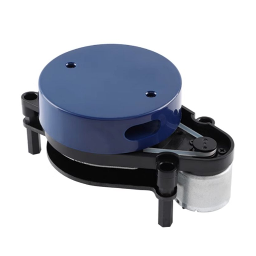
How a LiDAR Sensor Works on an Overhead Crane
LiDAR technology stands for Light Detection and Ranging. A LiDAR device fires out a pulsed laser beam, waits for the reflection off whatever happens to be in front of it, then calculates the distance from the speed of light and the time-of-flight formula d=c t/2. Most 2D LiDARs utilize a rotating mirror to scan the laser beam across a field of view, while 3D units use a rotating prism or MEMS mirror. Each scan produces a point cloud that the onboard algorithm converts into shapes, positions, and motion tracks.
How does a LiDAR sensor work for overhead cranes, specifically?
On an overhead crane, the LiDAR sensor is mounted on the end truck, bridge, or trolley and aims down the runway, the neighboring bay, or the area below the load. The point cloud generated is put through a real-time object detection algorithm that sorts obstacles into three categories – structural (rails, columns, racking), dynamic (other cranes, AGVs, pedestrians), and false echoes (steam, dust plumes). Object coordinates are then compared against user-defined warning, deceleration, and stop zones. When an obstacle breaches the warning zone, the LiDAR asserts a safety normally-open relay, a PROFIsafe message, or an EtherCAT FSoE packet that is read by the crane PLC within one scan cycle.
The most common wavelengths used on the industrial market are 905 nm and 1550 nm. 905 nm is less expensive and encapsulates the majority of IEC 61496-certified 2D safety scanners. Its 1550 nm cousin, evaluated side-by-side in a comparative study on ResearchGate, performs noticeably better in fog, dust, and rain, and permits more optical power under the auspices of eye-safety standards, which results in greater actual distance in steel mills, foundries, and outdoor gantry environments.
Essential point: 905 nm is the safe default for indoor bays under 40 m. Switch to 1550 nm when the air in your facility is not clean.
2D LiDAR vs 3D LiDAR for Overhead Cranes: Which One Fits Your Bay?
That 2D vs. 3D question is where most selection errors happen. In short, 2D LiDAR for an overhead crane works when hazards live on a single horizontal slice – bridge-to-bridge tandem approaches, end-of-rail stops, pedestrian barricades at deck level. 3D LiDAR needs to be deployed whenever workflow occurs over multiple levels, or higher/lower levels need to work around the sensor region, or the signal is blocked out by stacked-lumber viewing corners.
The difference in raw point density by the two sensor architectures is staggering. Most 2D industrial-grade scanners can be expected to generate 1,080 points per revolution. A 3D sensor in a similar pricing range will generate tens of thousands of points/sec at minimum, and current offerings like those from Ouster and Hesai can deliver as many as 1.2 million points/sec. A 2025 ScienceDirect study on object detection accuracy as a function of point cloud density found that cutting density by as little as 20% materially degrades detection precision, which is why down-sampling a 3D cloud is not a legitimate cost-cutting strategy.
For the worker detection issue specifically, the arxiv paper 2603.04938 from the TwinFlow project evaluated 3D LiDAR attached to a bridge crane and logged best-tuned detector configurations with an average precision (AP) of 0.84 out to 5.0 meters horizontally, reaching an AP of 0.97 at 1.0 meter distance. No comparable 2D product has those scores for the simple target of a person, because 2D cannot differentiate a worker from a pallet sharing a scan slice.
| Dimension | 2D LiDAR | 3D LiDAR |
|---|---|---|
| Coverage plane | Single horizontal slice | Volumetric (H × V) |
| Points per second | ~43,000 (1,080/rot @ 40 Hz) | 30,000 – 1,200,000 |
| Worker detection AP | Not classified reliably | 0.84–0.97 @ ≤5 m (arxiv 2603.04938) |
| Typical range | 5–40 m | 30–120 m |
| Installed unit cost | US$1,200–US$4,500 | US$4,800–US$14,000 |
| PLC compute load | Low — binary zone outputs | High — requires edge processor or onboard classifier |
| Best for | Horizontal travel-path protection, bridge-to-bridge | Worker intrusion, multi-level load paths, stacked yards |
If your requirement set is having tandem cranes avoid each other in a controlled-rail environment, 2D is the sensible claim, and the LiDAR units for overhead crane applications from Han TranVuong and colleagues team are built around 2D sensors with software configurable multiple detection zones. Once a worker’s projecting into your all-data work environment, move the money to 3D.
LiDAR vs Safety Laser Scanner vs Ultrasonic vs Radar: Sensing Technology Face-Off
A crane collision avoidance system can be designed using several sensing modalities, and equating them all is just as costly as ignoring essential considerations. Here is how the four main options compare over the performance metrics most relevant.
| Metric | LiDAR | Safety Laser Scanner | Ultrasonic | Radar (77 GHz) |
|---|---|---|---|---|
| Range | 0.5–120 m | 0.1–30 m | 0.05–10 m | 0.5–200 m |
| Angular resolution | 0.1–0.5° | 0.25–0.5° | 5–15° (wide beam) | 1–3° |
| Dust / steam tolerance | Moderate (905 nm) → Good (1550 nm) | Moderate | Good | Excellent |
| Functional safety cert | Often Type 3 ESPE, PL d | Type 3 ESPE, PL d Cat 3 per IEC 61496-1 | Rarely | Rarely |
| False-alarm rate | Low | Low | High (echo-prone) | Medium |
| Install cost per node | US$1.2k–14k | US$1.8k–5k | US$150–900 | US$900–4k |
Why choose LiDAR over ultrasonic or radar for overhead crane safety?
LiDAR is the best if angular resolution to below 1° combined with industrial safety certification is required. Ultrasonics are still viable for very-slow gantries below 0.5 m/sec if you require simple presence vs. absence in the far field, and radar is the sole choice if your working air is wet with water-steam or immersed in combustible dust, e.g. handling coal or grain and using a water quench, for example. For everything in the middle for a steel bay, machining area, or paper mill storage yard, LiDAR is the only sensing source that can give you the range to trespass, the features to classify in order to show you an actual worker, and can do so with a path that can earn your PLd certification using a Rockwell Automation compatible safety PLC.
Major lesson: tune wavelength of operation and classification category to your working air. Do not select solely on the basis of brochure specifications.
How to Spec the Sensor: Detection Range, Field of View and Point Density
An anti collision sensor for cranes has to be able to see far enough ahead that the brakes can stop the bridge before the obstacle. That is not a marketing claim – it is based on calculations using ASME B30.2-1.12.3(a)(1), which states that the brakes must be able to stop the trolley or bridge within a distance in feet equal to 10% of the rated load speed in ft/min.
📐 Worked example — minimum LiDAR range for a 20-ton bridge crane
Rated travel speed: 150 ft/min (≈ 0.76 m/s)
ASME B30.2 minimum braking distance = 10% × 150 ft = 15 ft (≈ 4.6 m)
Safety margin (reaction + sensor latency + zone overshoot): 3× multiplier
Minimum LiDAR warning-zone range ≈ 15 m (round up to a standard 20 m SKU)
Running the same math on a 30-ton bridge at 300 ft/min yields a 30 m minimum warning range, which is why long-range 2D scanners such as the Hokuyo UGM-50LAP (120 m, 190° field of view, IP67) exist — you need the headroom when the crane moves faster.
Field of view is the second spec to pin down. A 270° horizontal FoV covers both forward and reverse travel from a single sensor mounted on an end truck corner. A 190° unit needs to be paired – one forward, one back – as in the four-sensor gantry crane layout published by Dadisick, with the T1-T4 sensors mounted close to each drive wheel to avoid blind zones.
Point density is the third spec to pin down. For 2D scanners, 0.25° angular resolution over 270° gives 1,080 points per scan — enough to resolve a 15 cm object at 10 m range, which is typically the smallest target you need to detect. For 3D, target at least 64 vertical channels if the sensor must classify workers, and do not accept down-sampled output as a cost-cutting shortcut.
Main point: spec range from B30.2 braking math, FoV from the crane geometry, and point density from the smallest object you must classify. Never copy a spec sheet from a neighboring bay.
LiDAR Installation and PLC Integration on Overhead Cranes
A good installation turns a properly specified sensor into a safety function with long-term reliability; the wrong one can make for nuisance stops and false comfort. Our engineering team recommends this six-step workflow for installation of both retrofit sensor packages and new bridges:
- Mount the sensor on the most rigid mounting bracket you can find; end trucks see less vibration than the bridge mid span. Keep it away from festoons and other sources of resonant vibration; measured time-of-flight drift caused by resonant vibration is evident there first.
- Keep cables well protected from the festoon loop and the drive VFD. A sensor Ethernet cable receiving induced noise from a 400 A VFD makes random safety system failures. Use shielded cable and a dedicated conduit.
- Explicitly map the PLC I/O contract. Decide up front whether you will consume the sensor’s dry-contact safety relay or its digital bus – PROFIsafe, FSoE, or Ethernet/IP CIP Safety. Dry contact is simpler but gives you only binary zones, while the digital bus gives you object coordinates if you want to paint dynamic stop zones.
- Program warning, deceleration, and stop zones in that order. Warning = 1.5 braking distance. Deceleration = 1.2 braking distance. Stop = 1.0 braking distance plus a safety factor. Color-coded zones in the sensor configurator (blue, yellow, red) make the logic obvious at audit time.
- Commission with a rolling target, not a static cone. Static traffic cones are not a valid test. Push a cart at 1 m/s through each zone with a stopwatch and verify that the bridge decelerates or stops exactly where the configurator says it should.
- Get operator acceptance in writing. Any crane driver who signs off on nuisance stops on day three is the one who will disable the sensor on day thirty. Walk the operator through every zone boundary before commissioning closes.
“The fastest way to ruin a good LiDAR install is to hand it over without training the operator. Within a month, anyone who sees two false stops per shift will find a way to bypass the sensor, and your PL d rating becomes paper.”
Key takeaway: The install sequence is where most field failures originate. Cable routing, zone math, and operator acceptance carry as much weight as the sensor itself.
The 4-Factor LiDAR Selection Rule for Overhead Cranes 💡
If you remember nothing else from this guide, remember this framework. Good bridge crane anti collision system decisions collapse to four factors worth getting right. Rank your crane on each factor, add the scores, and the sum maps directly to a sensor tier.
| Factor | Score 1 — Low | Score 2 — Medium | Score 3 — High |
|---|---|---|---|
| 1. Crane Speed Class | < 60 ft/min | 60–200 ft/min | > 200 ft/min |
| 2. Hazard Topology | Single-plane (rail-only) | Mixed (rail + walkway) | Volumetric (workers + stacked loads) |
| 3. Environmental Tolerance | Clean indoor bay | Light dust / machine shop | Mill dust, steam, outdoor |
| 4. PLC Integration Depth | Dry-contact only | Ethernet/IP or PROFINET | CIP Safety / PROFIsafe / FSoE |
Sensor tier by total score:
- Entry tier (score 4-6): single 2D safety laser scanner at 905 nm, IP65 housing, 5-20 m range, dry-contact output. Installed cost runs US$3,500-6,000.
- Mid tier (score 7-9): paired 2D scanners with multi-zone programming, 905 nm, IP67, 20-40 m range, PROFINET or Ethernet/IP, PL d Cat 3 certification. Installed cost runs US$6,500-12,000.
- Premium tier (score 10-12): 3D LiDAR with onboard classifier, 1550 nm optics for the worst air, 40-120 m range, CIP Safety or FSoE bus. Installed cost runs US$12,000-18,000.
This rule is deliberately coarse – four factors, three tiers, twelve possible totals. That is the point. It is a first-pass filter you can run in a five-minute meeting before the vendor quotes arrive, and it will catch the worst under- and over-specification calls before the budget is locked.
Common Installation and Spec Pitfalls Engineers Miss
The following five field observations come from industry forums, post-incident reports, and our own commissioning visits. They are the errors that cost the most in rework and, occasionally, in safety incidents.
- Festoon vibration coupling is the silent killer. Mounting a lidar on an end-truck bracket near the festoon cable loop looks OK on a bench. When the bridge starts traveling, the low frequency oscillation of the festoon causes a slight angular drift in the sensor, and your zone boundaries start wandering. Solution: move the bracket to the end-truck top-plate, or add a tuned damper.
- Under-sizing the deceleration zone for worn brakes. ASME B30.2 specified braking distance is for a new crane. Field brakes drift as the brake band wears. Size your deceleration zone for 130% of the specified distance on inaugural day one cranes, 150% for fifty plus-year-old goliaths. That Reddit story about “knows-bad-brakes” overhead crane is the cautionary tale here.
- Using 2D where the stacked material creates vertical blind zones. A 2D scanner positioned at the roof beam on the runway has no awareness of the material that’s stacked up chest height ten feet ahead. On a Reddit thread in r/computervision, a developer posted about false triggers caused by bounding box overlap near the danger zone— where a human and a stack of painted board look the same to a 2D-only system. 3D, or a 2D-plus-3D combination, is the answer.
- Skipping commissioning in mill-dust conditions. Any scanner which performs with excellence during a dust-free commissioning run may degrade by fifty percent during critical normal operations. Commission at least once during a peak-production shift and log the zone performance.
- Missing EMC hardening on the crane power feed. Variable frequency drives controlling the hoist motor broadcast broadband noise that couples directly into the laser telemetry Ethernet cable. Use a foil-plus-braid shielded cable, a shielded RJ45 connector on both sides, and ground the shield to the crane structure only at the sensor end.
Main point: The sensor itself is only one variable. Mounting, cabling, EMC, and zone mathematics determine whether the solution lasts ten years or ten weeks.
Frequently Asked Questions
Is LiDAR for overhead cranes safe for workers walking below?
Yes. An industrial laser scanner certified to IEC 60825-1 Class 1 is safe for any amount of viewing time.
How much does a LiDAR crane anti-collision system cost per unit?
Installed costs fall into three brackets. Basic single 2D scanner solutions run US$3,500-6,000. Paired 2D scanner systems with multi-zone programming and PL d certification sell for US$6,500-12,000. Full 3D solutions with onboard classification, 1550 nm optics, and CIP Safety bus land at US$12,000-18,000 per crane, excluding engineering hours.
Can LiDAR work reliably in steel mills with heavy dust and heat?
Only if you specify 1550 nm optics and IP67 housings with built-in heaters. 905 nm scanners degrade visibly in airborne mill dust, and cheap IP65 boxes fog up on cold-start.
Does LiDAR replace limit switches or work alongside them?
Alongside. ASME B30.2 demand redundant end-of-travel limit switches as a fallback measure. Laser scanners add the active anti-collision layer which will grab you much earlier than any limit switch.
What certifications should an overhead crane LiDAR meet?
For non-European installations: IEC 61496-3 Type 3 ESPE classification, ISO 13849-1 Performance Level d (Category 3), SIL 2 according to IEC 61508, and CE designation. For European union installations:Machinery Regulation 2023/1230. For North American installations: refer to UL 61496 standards. If the datasheet omits listing all these certifications conjointly, the product is not a safety component – just a comfort component.
Can LiDAR enable fully autonomous overhead crane operation?
LiDAR is a necessary, not sufficient, condition for autonomy. Complete automation also requires position encoders, load sway control, fleet management software, and human-in-the-loop fallbacks.
Need help specifying a LiDAR solution for your overhead crane fleet?
Our team of engineers has specified, installed and commissioned crane LiDAR solutions for more than 20 years.
About this guide — research methodology
Cost ranges, detection distances, and performance numbers in this guide are compiled from publicly available OSHA records, the BLS 2024 Census of Fatal Occupational Injuries, ASME B30.2 standard documentation, IEC 61496 standard summaries, peer-reviewed research papers on point cloud density and person detection, and commissioning experience from our engineering team at CCH Shanghai Sensing Intelligence Technology. Exact numbers on your crane will depend on bridge span, duty cycle, brake wear state, and the air quality of your facility. Where a data point was sourced from a secondary aggregation rather than a primary record, the aggregating source is cited directly so readers can trace the chain.
References & Sources
- OSHA Accident Search Database — Overhead Crane Incidents — U.S. Department of Labor, Occupational Safety and Health Administration
- Census of Fatal Occupational Injuries Summary, 2024 — U.S. Bureau of Labor Statistics
- ASME B30.2: Safety Requirements for Overhead and Gantry Cranes — American Society of Mechanical Engineers
- ASME B30.2-2022 Overhead and Gantry Cranes Review — American National Standards Institute
- EN/IEC 61496-1 Electro-Sensitive Protective Equipment — Pilz Safety Standards Reference
- Person Detection and Tracking from an Overhead Crane LiDAR (TwinFlow project) — arxiv.org preprint, Business Finland and Aalto University
- Analysis of object detection accuracy based on the density of 3D point clouds — ScienceDirect peer-reviewed study, 2025
- Comparison of 905 nm and 1550 nm semiconductor laser rangefinders’ performance deterioration due to adverse environmental conditions — ResearchGate academic paper