Get in touch with QJKH Company
📐 Quick Specs: Safety Laser Scanner
| Device Classification | Type 3 ESPE per IEC 61496-3 (AOPDDR) |
| Safety Rating | SIL 2 (IEC 61508) / PLd Category 3 (ISO 13849-1) |
| Laser Class | Class 1 eye-safe (IEC 60825-1) |
| Scan Angle | 180°–275° typical; compact units often 270° |
| Protection Range | 3–8 m (warning zone up to 26 m) |
| Min Target Reflectance | 1.8% (per IEC 61496-3) |
| Response Time | 60–180 ms |
| Outputs | 2× OSSD redundant |
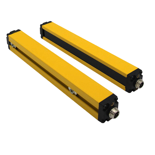
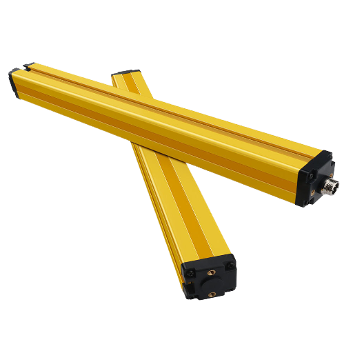
Safety laser scanners are the backbone of modern machine guarding in factory automation — replacing fi×ed guarding, safety mats, and in many cases light curtains. They scan a 2D plane with a rotating laser and stop nearby machinery when a person or object enters the protection zone. Unlike typical industrial sensors, they monitor themselves continuously per IEC 61496-3 and trigger a safe state on any internal fault.
This overview explains their underlying engineering principle (how do they work), the certification standards (IEC 61496-3, IEC 61508 SIL 2, ISO 13849 PLd), major specifications that differentiate models, the ISO 13855 mounting distance calculation, use with safety PLCs, and how to choose your scanner.
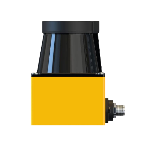
What Is a Safety Laser Scanner and How Does It Work?

A safety laser scanner is an Active Opto-electronic Protective Device responsive to Diffuse Reflection (AOPDDR), previously categorized as a Type 3 ESPE by IEC 61496-3. The “diffuse reflection” identifier indicates that it does not require a dedicated transmitter/receiver pair, and instead “receives reflection from any object scattering enough of its own emitted energy back to the detector.” A scanner detects any reflective surface scattering enough of its light back to the detector.
Working Principle
It does this by illuminating the field with a pulsed laser diode – usually operating at 905 nanometers in the near infrared, in a Class 1 eye safe output according to IEC 60825-1 – then measuring the time of flight of the reflected photons as they return to the detector. For each set of emitted pulses, the scanner measures a distance point against the known speed of light. Its output is a point cloud — a set of measured distances roughly oriented around the arc of the scanner’s coverage — generated very rapidly.
Once the distance points are established, the software defines a protection field – a polygon in the environment, surrounding the hazard – that will trigger the safety outputs in the scanner if any measured points falls within it with an adequate return signal.
Engineering Note: A Type 3 scanner measures thousands of distance points per revolution. Protection fields are defined in software as polygons — any intrusion within that polygon triggers the OSSDs within the published response time. Its shape can be irregular: L-shaped, notched, or curved to match the actual hazard boundary of your machine cell.
Self-Monitoring Redundancy
Under IEC 61496-3 the device itself must incorporate a self-checking function sufficient to Category 3 requirements. In reality, dual microprocessors operate independently of one another, each processing each scan and cross-comparing the resulting figures. If any inconsistencies are identified – whether optical byproducts, firmware or electronics error, or power supply fault – the scanner drops itOCOs OSSD outputs to its fail-safe state, safely halting your equipment. IEC 61496-3 imposes a 1.8% minimum target reflectance threshold, meaning even black or matte clothing will reflect enough light for the scanner to detect. This prevents operators from wearing dark clothing to evade detection.
Pro Tip: The dual processor design means a scanner that undergoes integrated self-test will actually fail safe; rather than missing detection and assuming a degraded machine state, it will halt the machinery as an integral part of failing the self-test. This fundamental difference between standard and safety-rated OM sensors.
4 device specification is published in IEC 61496-3:2018.
Safety Standards: IEC 61496, IEC 61508 SIL, and ISO 13849 PLd
Safety laser scanners are linked to a number of international standards, and each standard governs a different part of the SCS safety system. Knowing which standard regulates which function prevents failed specifications.
| Standard | Scope | Requirement for Safety Laser Scanners |
|---|---|---|
| IEC 61496-1 | General ESPE requirements | Baseline for all electro-sensitive protective equipment |
| IEC 61496-3:2018 | AOPDDR (diffuse reflection) | Type 3 — the governing standard for laser scanners |
| IEC 61496-2 | AOPD (beam interruption) | Type 2/4 — applies to light curtains, not scanners |
| IEC 61496-4 | VBPD (vision-based) | Type 4 — applies to camera systems, not scanners |
| IEC 61508 | Functional safety | SIL 2 — dangerous failure rate 10⁻⁷ to 10⁻⁶ per hour |
| ISO 13849-1 | Safety-related control systems | PLd, Category 3 — single fault tolerance |
| IEC 60825-1:2014 | Laser product safety | Class 1 eye-safe wavelength and power limits |
SIL 2 vs SIL 3 — Why Type 3 Scanners Max at SIL 2
SIL 2 represents a dangerous failure rate of between 10-10/hour. Type 3 scanners can be certified to SIL 2 because in the OSSD architecture, both OSSDs emanate from the same optical sensing element. To reach SIL 3 (10-10/hour) a safety function needs to be backed up by a truly independent second detection channel,the architecture used for Type 4 units.
Category 3 Architecture
ISO 13849-1 category 3 means it retains safety function in the event of a single fault. Cumulative faults could cause safety function failure, but any one fault must be detected before the next demand on the safety function (or during the next demand at latest). IEC 61496-3 Type 3 internal self-monitoring meets this requirement for the scanner hardware itself, but the total safety function, scanner to machine stop, must be validated at Category 3 including all intermediate components.
Caution: A Type 3 scanner should never replace a Type 4 device where the risk assessment determines SIL 3 / Category 4 safeguarding is necessary. Check the PLr you need against the rated PL of your scanner prior to choosing the device. Cost saving by choosing a lower rated device carries the risk of non-compliance liability.
In the majority of general machine safeguarding situations – the perimeter of a robotic workcell, packaging machinery, automated assembly – a Type 3 rated PLd / SIL 2 rated safety laser scanner is the correct and effective solution when the risk assessment dictates a PLr d.
Key Specifications: Detection Range, Resolution, and Response Time
Scanner specifications define both what the device will reliably detect as safe and at what distance from the hazard it must be placed. The table below summarizes key safety-related specifications, with typical ranges distilled from market datasheets for the generic Type 3 scanner category.
| Specification | Typical Range | Practical Meaning |
|---|---|---|
| Protection Field Radius | 3–8 m | Area where intrusion triggers safe stop |
| Warning Field Radius | up to 26 m | Advisory zone for slowdown or alarm signal |
| Scan Angle | 180°–275° | Coverage arc; maximum 275°FOV around the scanner unit |
| Angular Resolution | 0.1°–0.5° | Point-to-point angular precision |
| Detection Resolution | 30–70 mm | Minimum object size reliably detected at rated range |
| Response Time | 60–180 ms | Critical input to ISO 13855 safety distance calculation |
| Configurable Field Sets | up to 32 | Banks for direction switching or mode selection |
| OSSD Outputs | 2× redundant | Standard for Category 3 dual-channel safety |
| Operating Temperature | -10°C to +50°C | Industrial ambient range |
| Ambient Light Immunity | 10,000–40,000 lux | Indoor vs outdoor installation suitability |
Detection Resolution: Why It Matters More Than Range
Detection resolution is the minimum object size that the scanner is designed to reliably detect at its rated protection field radius. A 30 mm resolution scanner can consistently reliably detect a human hand or wrist in its detection zone – making it appropriate for close approach protection in hazardous areas. A 70 mm resolution scanner is sufficiently sensitive for reliably detecting crossing personnel (legs, torso) but may not be detect a reaching hand at the boundary of the protection field. (Note: the interaction of angular resolution and detection resolution is a geometrical calculation, based on the fact that at 4 m range a resolution of 0.33 is equal to a separation of about 23 mm between adjacent scan points – meaning the full-range protection field specification has to be taken from the datasheet, not calculated from the angular resolution specification.)
Good to know: a higher resolution (30 mm) allows hand level detection at the boundary of the protection field; specify 70 mm only where you intend to detect crossing workers, rather than reaching limbs, in your application. Detection resolution specification control the required protective distance D(C) for your ISO 13855 intrusion testing and subsequently the mounting distance.
Need to compare specific model specs side by side? Download the full specification comparison for CCH safety laser scanner models.
Primary Applications: Area Protection, Access Protection, and Collision Prevention
What are safety laser scanners used for? They cover three different modes of application, capitalizing on different properties of the configurable 2D protection field.
1. Area Protection — Stationary Machine Cells
The scanner is mounted horizontally at floor level or at a height such that the protection field intercepts the approaching object. It checks for presence of personnel in the danger zone around stationary, protected equipment such as robotic cells, presses, packaging equipment, automated palletizers. On the presence of a person or object, the OSSDs go to safe state and the machine stops. Its restart prevent feature retains the machine in safe state to protect personnel until the zone is clear and the operator restarts outside the zone.
Application example: Six-axis robot cell without physical safety fence. Per ISO 10218-2, the scanner defines a slow-down warning zone (machine drops to reduced speed) and an inner stop zone (machine stops). Maintenance mode allows operator entry with the safety function temporarily overridden via appropriate lockout/tagout procedure and safety-rated key switch.
2. Access Protection — Large Openings
Mounted vertically at the entrance to a hazard zone, the scanner replaces what would otherwise require multiple light curtain pairs to protect wide or irregular shaped openings. One scanner with 270 scan angle can protect an opening that might require three or four transmitter/receiver pairs of light curtains- eliminating hardware and mounting complexity and cost. The protection field polygon is programmed to match the opening precisely.
Application example: Unwinding machine with large infeed opening. The scanner confirms no operator is in the danger zone before restart. Combined with a GS-rated safety interlock switch on any secondary access door, this provides Category 3 access control across all entry points.
3. Collision Prevention — Mobile Platforms
Scanners are used to provide on vehicle collision avoidance on AGVs (Automated Guided Vehicles), AMRs (Autonomous Mobile Robots) and forklifts. Its programmable field sets (up to 32 of them) allow direction sensitive zone switching with the forward protection field enabled when traveling forward, the rear field when reversing, narrow lateral fields when moving normally and wide omnidirectional fields for parking and rotation maneuvers. External signals from the vehicle controller switch the active field set in an order monitored manner.
Pro Tip: Specify a scanner with environmental rating of IP65 or higher for AGV use and test the angular resolution at your maximum vehicle speed. At 1.5 m/sec vehicle speed and 80 ms scanner response, the vehicle moves 120 mm before scanner response can command a stop- include this in your safety distance calculation!
Safety Distance Calculation per ISO 13855

running the calculations for minimum safe distance from detection zone boundary to hazard point, this specification from ISO 13855:2024 can be a star, or more often, a boat anchor: getting your calculation wrong (reading the “total response time” value too low), results in a mounted distance that cannot reliably stop the machine before the operator reaches the hazard. This is the most common safety laser scanner installation problem.
The Formula
📐 S = K × T + C
S = minimum distance from detection zone boundary to nearest hazard point (mm)
K = approach speed of body part (mm/s)
T = total system response time (seconds)
C = intrusion distance — how far a body part penetrates before detection (mm)
Approach Speed (K)
- Hand/arm approach: K = 2,000 mm/sec (default from ISO 13855:2024)
- Use K = 1,600 mm/sec (ISO 13855:2024 correction to allow longer reach)
- Whole-body (walking) approach: K = 1,600 mm/s
Intrusion Distance (C) by Detection Resolution
- Hand detection (d 40mm): C = 8 (d 14) mm, 0 mm minimum
- Body detection (d 40 mm): C = 850 mm (average from ISO 13855)
Total Response Time (T)
Where: T represents the sum all of the delays in the safety chain, from the moment a person enters the detection zone until the moment the hazard stops:
- Scanner response time (from datasheet, e.g., 80 ms)
- Safety controller response time (e.g., 10 ms)
- Actuator / machine brake stopping time (e.g., 120 ms)
📐 Worked Example:
Scanner response: 80 ms | Safety PLC: 10 ms | Machine brake: 120 ms
T = (80 + 10 + 120) ms = 210 ms = 0.210 s
Detection resolution d = 70 mm (body detection)
C = 850 mm
K = 2,000 mm/s (hand approach, initial)
S = 2,000 × 0.210 + 850 = 420 + 850 = 1,270 mm
Verify: S = 1,270 mm. 500 mm keep K = 2,000 mm/sec. Final minimum mounting distance from hazard point would be 1,270 mm.
If d = 30 mm (hand detection): C = 8 × (30 − 14) = 128 mm → S = 420 + 128 = 548 mm
Notes on performance: A scanner’s published response time is just the component contribution. Each link in the safety chain — scanner, controller, actuator — adds to T. Under assess T produces an short mounting distance & unsafe installation. Always obtain stop time from your machine brake test, not a generic spec.
Reference: ISO 13855:2024- Positioning of safeguards with respect to the approach speeds of parts of the human body.
Need help verifying your safety distance for a specific installation? Our engineering team can review your application parameters.
Integration with Safety Controllers: CIP Safety, PROFIsafe, and OSSD Wiring
How a safety laser scanner is integrated into the overall safety system depends on your safety PLC network, the amount of zone data you need to transmit, and the need for remote diagnostics.
Integration Approaches
Hardwired OSSD: Scanner two OSSD channels are wired directly to a safety relay or safety PLC dual-input channel. simple, very reliable, easily configured for small cells with 1 scanner, no zone data needed. Both OSSDs must both be active for the safe state- a drop of any one channel puts the system into safe mode.
Safety Fieldbus: The use of a dedicated safety network cable to carry both the OSSD signal & diagnosis/ zone data makes for less wiring & enables concurrent multi-zone status display in the safety PLC HMI.
| Protocol | Ecosystem | Typical Applications |
|---|---|---|
| CIP Safety | Rockwell / Allen-Bradley (EtherNet/IP) | North American automotive and packaging lines |
| PROFIsafe | Siemens / PROFINET | European manufacturing facilities |
| FSoE (Safety over EtherCAT) | Beckhoff / EtherCAT | High-speed motion control systems |
| OSSD hardwired | Any safety PLC | Legacy integration, smaller cells |
Integration Gotcha – EDS/GSD File Compatibility: For CIP Safety integration, scanner manufacturers provide an EDS (Electronic Data Sheet) file that registers the device in the Rockwell Studio 5000 hardware catalog. As of 2024, Rockwell has been restricting third-party EDS file registration for some device categories, which may require configuring the scanner as a Generic Ethernet Module rather than using the native EDS entry. Confirm EDS compatibility with your specific Studio 5000 version prior to ordering- this has been a source of project delays.
OSSD Wiring Fundamentals
OSSD (Output Signal Switching Device) outputs are two independent PNP transistor channels. Both must be HIGH (24 VDC) for the safe-active state. When either drops, the connected safety input perceives a faulty condition & halts the connected machine function. The safety PLC OSSD input circuits also monitor cross-channel shorts & shorts to 24 VDC- both of which are wiring faults that must be corrected before restart is permitted.
Selection Framework: Matching Type 3 Scanner to Your Application
As with any safety device, complete a risk assessment in ISO 12100 & ISO 13849-1 determine required PLr. That PLr is the required input for device selection- not the make & model of scanner, not the marketing attributes of the device, not what was previously utilized on a similar project.
✔ Selection Checklist
- 1. What is your PLr? Complete risk assessment in ISO 13849-1. PLr d Type 3 scanner acceptable. PLr = e requires alternative device architecture.
- 2. What detection resolution will be needed? Body detection (>70 mm) for worker access zone; hand detection (30 mm) for close approaching; finger detection (<14 mm) for Type 4 light curtain.
- 3. Fixed or mobile installation? Mobile (AGV/AMR) field set bank switching with direction sensors. Fixed single or dual zone configuration.
- 4. What protocol does your safety PLC use? Match CIP Safety / PROFIsafe / FSoE / hardwired OSSD to avoid integration friction.
- 5. What is the ambient environment? Outdoor or high-sunlight require 40,000 lux ambient light immunity and IP65+ enclosure rating.
When Type 3 Is NOT Sufficient
- Press brakes requiring SIL 3 finger detection Type 4 AOPD (safety light curtain)
- Applications where risk assessment requires Category 4 architecture dual-channel Type 4 systems
- Any application where PLr = e is the risk assessment result
When Type 3 Is the Right Choice
- AGV navigation and on-vehicle obstacle detection
- Area access monitoring where operators walk through the zone (not reaching into a close hazard)
- Stationary robot cell perimeter with configurable slow-down and stop zones
- Large or irregular openings where light curtain pairs would be impractical
- Any installation where PLr d is confirmed by risk assessment
Critical Reminder: Before specifying any safeguarding device, complete a risk assessment per ISO 12100 / ISO 13849-1. The assessed PLr drives device selection – not marketing claims, not cost targets, and not the preference of the machine builder. This is a legal and safety requirement in all major markets.
Frequently Asked Questions

What is a safety laser scanner used for?
Safety laser scanners serve three primary functions in industrial settings. First, area protection around stationary machinery – monitoring a defined zone for personnel intrusion and stopping the machine when the zone is breached. Second, access protection at openings where operators enter hazard zones, replacing or supplementing physical barriers. Third, collision prevention on mobile platforms including AGVs, AMRs, and forklifts, using configurable 2D protection fields and self-monitoring redundancy per IEC 61496-3. All three applications share the same underlying time-of-flight detection and self-monitoring architecture.
What is the difference between Type 3 and Type 4 safety devices?
Type 3 devices – safety laser scanners – detect via diffuse reflection from the target itself. The target reflects the scanner’s own laser pulse back to its detector. They certify to SIL 2 / PLd per IEC 61496-3. Type 4 devices use beam interruption (light curtains, per IEC 61496-2) or image sensing. Type 4 certifies to SIL 3 / PLe. Type 4 is required when the risk assessment indicates PLr = e – such as press brakes with finger-level detection at close range. Most general machine guarding applications specify Type 3 as adequate when paired with appropriate safety distance calculation per ISO 13855, because the risk level does not require the higher SIL 3 architecture.
Do safety laser scanners need periodic testing?
Yes. ISO 13849 Category 3 requires diagnostic testing within a defined interval. Scanners self-test continuously via internal redundancy, but the full installed safety function – from scanner OSSD output through safety controller to machine actuator stop – requires documented periodic verification. Most installations run monthly functional tests (trigger the scanner, confirm machine stops within expected time) and annual full-scope safety validation with documented records.
Can safety laser scanners work outdoors?
Only models with proven outdoor ambient light immunity (generally 40,000lux or greater) and IP65 + environmental protection are suitable for outdoor installation. Typical indoor scanners specify 10,000-20,000lux immunity which is inadequate in direct sunlight (to 100,000lux). Rain, particulate in the airstream can also cause false stops in an unsuitable scanner. Confirm the manufacturers ambient light specification before outdoors specification against maximum sunlight conditions at your installation location.
How do safety laser scanners compare to light curtains?
Light curtains(Type 2 or Type 4 AOPD according to IEC 61496-2) consist of transmitter / receiver matching pairs projecting a number of parallel beams through a fixed detection plane. Safety laser scanners (Type 3 AOPDDR according to IEC 61496-3) have a single enclosure with a 2D configurable protection zone polygon. Scanners allow custom zone shape selection and easier installation through large or irregular openings. Light curtains provide higher safety ratings – up to SIL 3 / PLe for Type 4 – and can have faster response times making them suitable for also do close-approach finger detection applications (where Type 3 is not fast enough). For a full safety light curtains comparison table see the comparison guide.
What is SIL 2 and why does it matter for safety laser scanners?
SIL stands for Safety Integrity Level according to IEC 61508. SIL 2 is defined as possible dangerous failure rates between 10 and 10per hour of operation. Safety laser scanners certify to SIL 2 which is sufficient for most machine guarding applications when the risk assessment confirms PLr d. For applications requiring the base safety performance and compliance of SIL 3 / PLe with dangerous failure rates below 10per hour require device architectures with a truly independent second detection zone, such as dual-channel Type 4.
Looking for Certified Safety Laser Scanner Solutions?
CCH Shanghai Sensing Intelligence Technology builds safety solutions – our safety laser scanners comply with IEC 61496-3, SIL 2 and PLd requirements. 20+ years of safety sensing manufacturing experience, OEM services that customize units to vendor specifications, free test samples for real-time evaluation before pre-order.
About This Guide
CCH Shanghai Sensing Intelligence Technology Co., Ltd builds industrial safety sensors including safety laser scanners in our Hangzhou Airport Economic Demonstration Zone manufacturing location. References to international published standards (IEC 61496-3, IEC 61508, ISO 13849-1, ISO 13855, IEC 60825-1) or industry published specifications are used to support this guide. Numerical references to specific ranges always refer to general industry field performance from multiple manufacturers and should be validated against the datasheet and accompanied by a risk assessment per the ISO 12100 to qualify the device.
References & Standards
- IEC 61496-3:2018 — Safety of machinery — Electro-sensitive protective equipment — Part 3: Particular requirements for equipment using protective measures based on diffuse reflection — International Electrotechnical Commission
- ISO 13855:2024 — Safety of machinery — Positioning of safeguards with respect to the approach speeds of parts of the human body — International Organization for Standardization
- ISO 13849-1 — Safety of machinery — Safety-related parts of control systems — Part 1: General principles for design — International Organization for Standardization
- IEC 61508 — Functional safety of electrical/electronic/programmable electronic safety-related systems — International Electrotechnical Commission
- IEC 60825-1:2014 — Safety of laser products — Part 1: Equipment classification and requirements — International Electrotechnical Commission
Related Articles
- Safety Light Curtains vs Safety Laser Scanners: Type 2, Type 4, and Application Guide
- Safety Relay Modules: Selection Guide for OSSD-Connected Safeguarding Devices
- Industrial Safety Sensors Overview — CCH Shanghai Sensing Intelligence Technology
- Lidar Sensors for Industrial Automation: Navigation, Mapping, and Obstacle Detection