Get in touch with QJKH Company
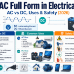
If you’ve ever flipped a light switch or plugged in a tool, you’ve used AC. The AC full form in electrical engineering is Alternating Currentan electric current that periodically reverses direction and changes magnitude over time, unlike direct current (DC), which flows steadily one way. This guide explains what AC is, how it differs from DC, what a sine wave actually tells you, why the grid runs on AC, and, for the engineers who keep machines safe, what happens to a safety circuit when AC power drops. (Updated June 2026.)
AC stands for Alternating Current. It’s the electric current supplied by the power grid to homes, offices, and factories, where the voltage rises, falls, and reverses in a smooth sine wave 50 or 60 times per second. AC is preferred for transmission because transformers can raise and lower its voltage cheaply.
AC Quick Facts
| Full form | Alternating Current |
| Not to be confused with | “AC” the air conditioner (same letters, different thing) |
| Waveform | Sine wave (reverses periodically) |
| Frequency | 50 Hz (most of the world) / 60 Hz (North America) |
| Typical mains | 120 V / 230 V single-phase; 400–480 V three-phase |
| Opposite | DC (Direct Current) — one direction, constant level |
💡 Key Points
- AC didn’t win because it’s inherently “better” than DC, it won because transformers could step its voltage up cheaply for low-loss transmission, an edge that’s now eroding.
- AC reverses direction; DC doesn’t. Almost every device that plugs into a wall converts AC to DC internally.
- For a sine wave, RMS voltage equals peak divided by √2, 120 V RMS mains actually peaks near 170 V.
- In a machine-safety circuit, losing AC power isn’t a failure to avoid but a state to design for: the circuit should fall to a defined safe state.
What Is the Full Form of AC in Electrical?
In electrical engineering, AC stands for Alternating Current: an electric current that changes direction periodically, its direction reverses and its magnitude rise and falls continuously over time. Britannica describes it as a flow of electric charge that “starts from zero, grows to a maximum, decreases to zero,” then reverses and repeats.
That repeating reversal is the whole point, it’s what separates AC from direct current, where charge moves steadily in one direction like water from a tank (see MSU College Physics on AC versus DC).
One source of confusion is worth clearing up immediately. In an electrical context, “AC” means Alternating Current; the household “AC” is an air conditioner. They share the same two letters and nothing else, though the air conditioner is, of course, powered by electrical AC. This article is about the current, not the cooler.
⚠️ One-line aside
The rock band AC/DC took its name from the AC/DC label on a sewing machine — a nod to the two kinds of electrical current, not the other way around.
AC vs DC: What’s the Difference?
AC and DC differ mainly in direction. Alternating current reverses direction many times per second and traces a sine wave; direct current flows in one direction at a steady level, the way a battery deliver power. That single distinction cascades into almost every practical difference between the two, from how each is transmitted to which one runs your laptop. The table below, call it the AC-vs-DC Trade-Off Ledgerlays the two side by side.
| Dimension | AC (Alternating Current) | DC (Direct Current) |
|---|---|---|
| Direction | Reverses periodically | One direction only |
| Waveform | Sine wave (also square/triangle in electronics) | Flat, constant level |
| Frequency | 50 Hz or 60 Hz | 0 Hz (no cycling) |
| Voltage change | Easy and cheap with a transformer | Needs power electronics (historically hard) |
| Long-distance transmission | Efficient at high voltage | Now efficient via HVDC, but costly converters |
| Generation source | Alternator / spinning generator | Batteries, solar cells, rectified AC |
| Energy storage | Not stored directly | Stored in batteries |
| Conversion device | Inverter makes AC from DC | Rectifier makes DC from AC |
| Typical uses | Grid power, motors, lighting, heating | Electronics, batteries, solar, EVs, control circuits |
| Shock profile | At 50/60 Hz, raises let-go and fibrillation risk (see safety section) | Tends to cause a single contraction; severity still depends on voltage and path |
Choose AC or DC?
Choose AC when you need to move power over distance, run large motors, or change voltage with a transformer. Choose DC when you need a stable level for electronics, batteries, solar, or low-voltage machine control. In practice you rarely pick one, most systems use AC to deliver power and DC inside the device.
Are AC and DC interchangeable in a device?
No, devices don’t simply “accept both.” A laptop, phone charger, or industrial control panel takes AC from the wall and converts it to the DC its electronics need. Feeding DC into an AC-only motor, or AC into a DC-only board, damages equipment. These two coexist by conversion (rectifiers and inverters), not by interchangeability, a point we return to below.
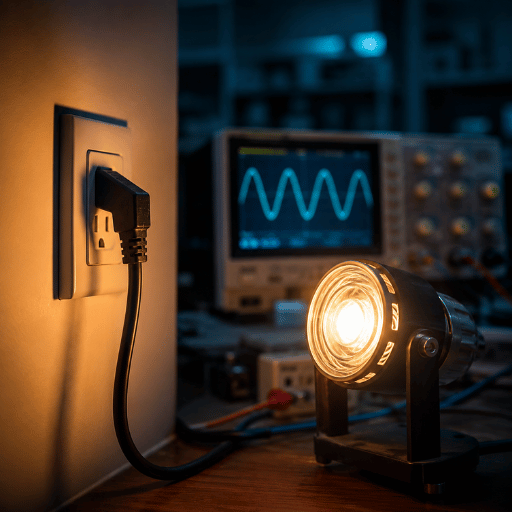
AC Waveform Signature Panel: Sine Wave, Frequency & RMS
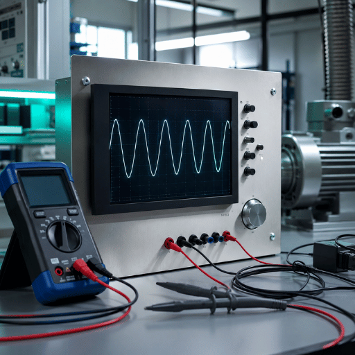
An AC waveform is described by a small set of measurable quantities, its “signature readings.” Read together, frequency, period, peak voltage, and RMS voltage tell you everything practical about a sine wave: how fast it cycles, how high it swings, and the single number a meter reports. Those quantities are gathered in the panel below.
| Quantity | Symbol | What it means | Typical value (US mains) |
|---|---|---|---|
| Frequency | f | Cycles per second | 60 Hz |
| Period | T | Time for one cycle (1/f) | 16.7 ms |
| Peak voltage | Vpk | Maximum in one direction | ~170 V |
| Peak-to-peak | Vpp | Top to bottom swing | ~340 V |
| RMS voltage | Vrms | Effective heating value; what a meter reads | 120 V |
| Average value | Vavg | Mean over a full cycle (zero for a pure sine) | 0 V |
| Amplitude | A | Height from zero to peak | ~170 V |
| Phase angle | φ | Shift relative to a reference wave | 0–360° |
| Waveform shape | — | Sine (mains); square/triangle in electronics | Sine |
📐 Engineering Note — the RMS calculation
For a pure sine wave, RMS voltage equals peak voltage divided by the square root of two: Vrms = Vpk ÷ √2. Work it the other way to see why “120 V” and “170 V” are both correct: 120 V RMS × √2 ≈ 170 V peak. In Europe, 230 V RMS × √2 ≈ 325 V peak. That √2 ≈ 1.414 factor is why a meter labeled 120 V sits across conductors that actually swing to roughly ±170 V.
The catch: Vrms = Vpk/√2 holds only for a clean sine wave. Variable-frequency drives, switch-mode supplies, and harmonic-rich loads distort the waveform, so a simple peak reading no longer converts cleanly, that’s exactly what a true-RMS meter is for (the University of Massachusetts derives the RMS relationship). On a factory floor, assume distorted AC and measure with true-RMS.
Why Does the Grid Run on AC? The War of the Currents
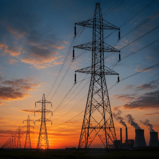
The grid runs on AC because of one cheap trick: a transformer can raise and lower AC voltage with almost no moving parts, and high voltage is the key to low-loss power transmission, the ability to transmit power over long distances without wasting most of it as heat.
The US Department of Energy puts it plainly, AC “can be converted to different voltages relatively easily using a transformer,” while DC “isn’t easily converted to higher or lower voltages.” That sentence, not any inherent superiority, decided the outcome.
Here’s the chain of reasoning, walked all the way through. Power lost as heat in a wire equals current squared times resistance (Ploss = I²R). For a fixed amount of delivered power, raising the voltage lets you carry the same power at lower current, and because the loss depend on current squared, the payoff is dramatic. Step the voltage up ten times and the current drop to one-tenth; the I²R loss falls to one-hundredth. So a power plant can sit hundreds of miles from a city, push electricity through high-voltage lines, and step it back down near the load, something early DC, which couldn’t change voltage cheaply, simply couldn’t do.
That advantage settled the “War of the Currents” of the late 1880s. Thomas Edison had built a network of local DC stations, each limited to roughly a mile of reach. George Westinghouse, holding Nikola Tesla’s AC patents, bet on transformers and long-distance transmission. According to the Rutgers Thomas A. Edison Papers, Tesla “sold Westinghouse the rights to a motor that made AC useful for driving machinery,” and Edison’s own company later had to license those patents from Westinghouse. When alternating current from Niagara Falls lit Buffalo on November 16, 1896, the argument was effectively over.
But notice the contrarian thread the modern reader should carry forward: AC won on transformability, not on being fundamentally better. The Department of Energy itself frames today’s picture as a “hybrid armistice” — computers, LEDs, solar cells, and electric vehicles all run on DC, and HVDC now moves power long distances with less loss. We pick that thread up in the outlook section.
Single-Phase vs Three-Phase AC: The Power Dividend
Single-phase AC uses one alternating waveform; three-phase AC uses three, each offset by 120 degrees, sharing a set of conductors. Homes run on single-phase (120 V or 230 V); factories run on three-phase (commonly 400–480 V). The reason industry insists on three-phase is what you might call the Three-Phase Power Dividend: three overlapping waveforms deliver near-constant instantaneous power instead of one that pulses to zero twice per cycle, and they carry more power per conductor (University of Louisville, Three-Phase Power).
That dividend isn’t abstract. Practitioners point out, correctly, that three-phase AC “allows the use of polyphase induction motors, which are impossible to run directly on a DC power grid.” A three-phase motor is self-starting and runs smoothly because the rotating field never collapses to zero, which is precisely why conveyor lines, pumps, compressors, and CNC spindles are three-phase. A small workshop on single-phase can convert to three-phase with a phase converter or a variable-frequency drive when it adds that first large motor, a common, concrete upgrade decision.
| Feature | Single-phase | Three-phase |
|---|---|---|
| Waveforms | One | Three, 120° apart |
| Typical voltage | 120 V / 230 V | 400 V / 480 V |
| Power delivery | Pulses to zero twice per cycle | Near-constant |
| Motor starting | Needs a start capacitor/winding | Self-starting |
| Typical use | Homes, small offices | Industry, large motors |
How AC Is Generated and the Machines It Runs
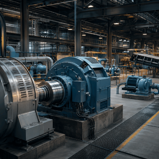
AC is generated by spinning a coil inside a magnetic field, the basic principle of every alternator in every power plant. A turbine driven by steam, water, or wind rotates the coil; because the coil passes through changing magnetic polarity, the induced voltage rises, reverses, and falls in step with the rotation. That’s why generated electricity is alternating by nature, the geometry of a rotating machine produce a sine wave automatically.
That same physics runs in reverse inside an AC motor: feed alternating current into windings and the resulting rotating field turns a shaft. Transformers, meanwhile, depend on AC specifically because they work only on a changing magnetic flux, a steady DC current produces no changing field and so can’t be transformed at all. Generators, motors, and transformers are the three workhorses that make an AC grid possible, and each one exploits the same reversing field that defines alternating current.
“On a plant floor, the reason almost everything upstream of the control cabinet is AC is mechanical: motors, transformers, and generators all run on a rotating or changing magnetic field. The DC only appears once you are inside the electronics.”
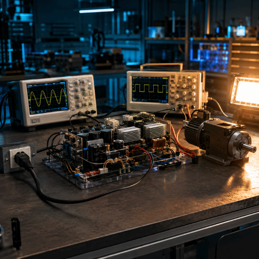
Converting AC to DC and Back: Rectifiers & Inverters
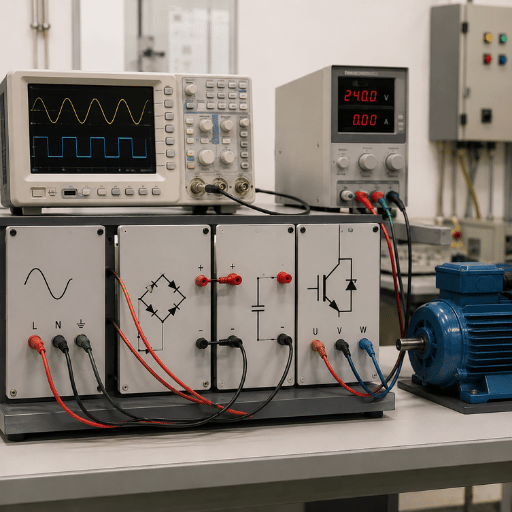
Two devices bridge the AC and DC worlds: a rectifier turns AC into DC, and an inverter turns DC into AC. Your phone charger and any computer power supply are rectifiers, they take wall AC and produce the steady DC that chips require. A solar array or a UPS does the opposite: an inverter converts its DC into grid-compatible AC. This is why “AC or DC” is rarely an either/or question in real equipment; most systems use both, joined by a converter.
That conversion isn’t free. Each AC-to-DC and DC-to-AC stage loses a little energy as heat, which is why engineers count conversion stages when they design efficient systems. USPTO patent filings for HVDC converter systems, for example, designs that pair a rectifier and an inverter through a multi-bridge stage, exist precisely to move power as DC over long distances and then hand it back to the AC grid. For a buyer, the takeaway: when you see “AC adapter,” “rectifier,” or “inverter” on a datasheet, you’re reading the seam where these two forms of current meet.
Where AC Power Is Used: Homes, Industry & the Grid

AC is used almost everywhere electricity is delivered: from the power plant, through transmission lines and substations (Stanford Understand Energy), to the outlets in your wall. Residential supply is single-phase at 120 V (North America) or 230 V (most of the world); commercial and industrial buildings add three-phase at 400–480 V for heavy loads. The current alternates 60 times per second in North America and 50 times per second across most of Europe, Asia, and Africa.
What is the frequency of AC in most countries?
Most countries supply AC at 50 Hz; North America and parts of South America and Asia use 60 Hz. That difference is historical, not technical, but it matters for equipment: a motor or clock designed for 60 Hz runs slightly slow on 50 Hz, and imported machinery must be specified for the local frequency. For an exporter shipping to multiple regions, frequency is one of the first compatibility questions to settle.
AC Power in Machine-Safety Circuits: The AC-Loss Safe-State Sequence in 4 Steps
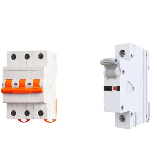
In an industrial machine, AC mains does two jobs: it powers the motors and it feeds the control and safety circuits, usually through a control transformer that steps 400–480 V AC down to a control voltage such as 230 V AC or 24 V DC. The safety question isn’t only “what does AC do when it’s present” but “what happens when it drops.” A well-designed safety circuit treats loss of AC as a defined event, not an accident.
That’s the idea behind what we call the AC-Loss Safe-State Sequence: when AC mains sags or fails, a monitored safety function, a safety relay, an OSSD output from a light curtain, a Category 3 or 4 architecture, should de-energize and drive the machine to a defined safe state rather than freeze unpredictably. In practice the sequence run in four steps:
- AC mains sags or drops below the control transformer’s threshold.
- The monitored safety relay de-energizes and its contacts open.
- The OSSD outputs go low, commanding the machine to stop.
- The machine settles into its defined safe state and holds there until power returns and a deliberate reset confirm it’s safe to restart.
The principle is “de-energize to trip”: the safe condition is the powered-off condition, so a power loss is the safe response. The current edition of the machinery electrical-safety standard, IEC 60204-1:2018 (with its 2025 amendment, A1:2025), governs exactly how machine control circuits must behave on supply interruption and restoration.
⚠️ Honesty caveat
This section is about power continuity to a safe state, not about which guard or sensor a given machine needs. Safeguard selection is machine-specific and governed by risk assessment (ISO 12100) and local rules such as OSHA 1910.212, a presence-sensing device is not valid on every machine type. Match the safeguard to the hazard first; treat AC-loss behaviour as a property of the control circuit you have chosen.
Is AC actually more dangerous here? At mains frequency it can be. Alternating current at 50–60 Hz is particularly effective at disrupting the heart’s rhythm, and the international standard on the effects of current on the human body, IEC 60479-1:2020, uses AC in this band as the reference for ventricular-fibrillation thresholds. But the danger is not “frequency alone.” The US National Institute for Occupational Safety and Health (NIOSH) is explicit that shock severity depends on voltage, the body’s resistance, the current path, contact duration, and the person’s condition, not on AC versus DC by itself. The practical lesson for a safety integrator is to design the de-energized state to be the safe one, and to choose control voltages and safety relay modules accordingly. For the wiring and product side of this, see our guide to safety relay modules and the broader set of industrial safety solutions that monitor these circuits.
A concrete scenario make the sequence tangible. On a press cell a CCH Shanghai Sensing team supported, the control transformer fed a 24 V DC safety relay from a 400 V AC supply; when a brownout dropped the AC, the relay’s monitored contacts opened, the OSSD pair went low, and the press stopped at top-dead-center rather than mid-stroke, the safe state by design, not by luck. Wiring an emergency stop and relay to reach that same state is covered in our note on the emergency stop safety relay, and the performance-level logic sit within the functional safety standards family.
AC vs DC Outlook 2026: Is DC Making a Comeback?
The most important shift to watch is that the AC-versus-DC balance is tilting, selectively, back toward DC for specific high-density loads, while AC keeps the grid. That driver is concrete: surging power density in AI data centers makes repeated AC-to-DC conversion wasteful, and renewables plus batteries are natively DC, so removing conversion stages saves real energy.
This is a procurement-relevant judgment, not a market slogan: when you specify new control or power architecture in 2026, it’s now worth asking whether a DC bus removes a conversion stage you would otherwise pay for in losses.
On the technology side, the evidence is specific. NVIDIA’s 800 VDC data-center reference architecture reports that, at 800 VDC, “the same wire gauge can carry 157% more power than 415 VAC,” with AI racks approaching a megawatt each and the design eliminating several inefficient AC-to-DC steps; Hitachi Energy announced a matching grid-to-rack 800 V architecture in October 2025. National laboratories have studied 380 V DC distribution in data centers for years, and the US Department of Energy notes that future buildings may use “a balance of AC and DC.” Treat these as leading-edge forecasts and vendor designs, not settled grid-wide facts, AC still runs generation, transmission, distribution, and the vast installed base of motors.
For background scale only: analysts such as Goldman Sachs project US data-center power demand climbing from roughly 31 GW in 2025 toward the mid-60s GW by 2027, and the International Energy Agency estimates data centers remain below roughly 10% of global electricity-demand growth this decade, large enough to drive niche DC adoption, not large enough to displace AC. The honest summary is the one the Department of Energy already uses: a hybrid armistice, in which AC and DC each keep the jobs they do best.
Frequently Asked Questions
What is the full form of AC in electrical?
View Answer
In electrical engineering, AC stands for Alternating Current — an electric current that periodically reverses direction and changes magnitude over time, drawn as a sine wave. It is the form of power the grid delivers to homes, offices, and factories, and it is the type of electricity most large equipment runs on. It is not the household air conditioner, which shares the abbreviation only.
What is the difference between AC and DC?
View Answer
Alternating current reverses direction periodically and flows as a sine wave; direct current flows steadily in one direction, like a battery. AC suits the grid, motors, and long-distance transmission because transformers change its voltage easily. DC suits electronics, batteries, solar, and low-voltage control. Most equipment uses AC to receive power and DC inside, joined by a rectifier or inverter.
Is the electrical “AC” the same as an air conditioner?
View Answer
No. In electrical terms, AC is Alternating Current — a type of current. An air conditioner is a machine that is also abbreviated “AC,” but the two are unrelated apart from the letters. An air conditioner is, in fact, powered by electrical AC, which is where the shared shorthand causes confusion.
Why can’t we use DC for long-distance transmission?
View Answer
Historically, the problem was voltage. Low-loss transmission needs very high voltage, and transformers could step AC voltage up and down cheaply while DC could not be converted economically. So AC became the transmission standard. That has changed: high-voltage direct current (HVDC) now moves power over very long distances with less loss than AC, but it requires costly converter stations at each end, so it is reserved for specific long links rather than the general grid.
Is AC more dangerous than DC?
View Answer
At mains frequency (50–60 Hz), AC is more likely to cause a “can’t let go” muscle reaction and to trigger ventricular fibrillation than direct current does. But the overall severity of a shock depends on the voltage, the path the current takes through the body, and how long contact lasts — not frequency alone.
What is the frequency of AC in most countries?
View Answer
Most of the world supplies AC at 50 Hz, while North America and parts of South America and Asia use 60 Hz. The figure tells you how many times per second the current reverses direction. It matters in practice because motors, clocks, and timing-sensitive equipment are designed for one frequency: a 60 Hz motor runs about 17% slower on 50 Hz, and machinery bought abroad must be specified for the local supply frequency before it is installed.
Designing machine-safety circuits that handle AC loss?
CCH Shanghai Sensing (QJKH) builds the safety light curtains, safety laser scanners, and safety relay modules that hold a machine in a defined safe state when AC power sags or drops. If you are choosing control voltages or designing safe-state behaviour for a new machine, our engineering team can help you wire the safety circuit to fail safe on loss of power.
Why We Cover AC Fundamentals
AC power is not a product we make, we build machine-safety sensors and relays. We wrote this because the questions our integration customers ask most often start here: what control voltage to step the mains down to, and what a safety circuit should do when AC drops. The safe-state framing in this guide reflects how the CCH Shanghai Sensing technical team wires monitored safety functions to fail safe on power loss, under IEC 60204-1 and the functional-safety standards.
References & Sources
- The War of the Currents: AC vs. DC PowerU.S. Department of Energy
- Alternating current, Definition & FactsEncyclopædia Britannica
- Alternating currentWikipedia (RMS, waveform, three-phase, HVDC overview)
- The Current WarsThomas A. Edison Papers, Rutgers University
- Connecting the Country with HVDCU.S. Department of Energy, Office of Electricity
- Direct Current (DC) in Buildings and the Smart GridU.S. Department of Energy
- 380 Vdc Architectures for the Modern Data CenterLawrence Berkeley National Laboratory
- Worker Deaths by Electrocution (electrical injury factors)NIOSH, U.S. Centers for Disease Control and Prevention
- Energy demand from AIInternational Energy Agency
- IEC 60479-1:2020, Effects of current on human beings and livestock, and IEC 60204-1:2018/A1:2025, Safety of machinery, Electrical equipment of machinesInternational Electrotechnical Commission
Related Articles
- UPS full form in electricalbackup power and the safety-circuit hold window
- Light curtain safety relaywiring OSSD outputs to a monitored relay
- ISO 13849 performance leveldetermining required PL for a safety function