Get in touch with QJKH Company
A safety light curtain wiring diagram is simple on paper: two output wires, a 24VDC supply, and a ground. In the panel it’s seldom so. Those two output wires are OSSDs – Output Signal Switching Devices – and how you terminate them determines whether the curtain actually stops the hazard or just trips at random. This guide walks the wiring from the curtain terminals all the way into a safety relay, a Allen-Bradley GuardLogix controller, and a Siemens SIMATIC fail-safe PLC, with the field details that the usual single page diagrams omit.
Most published diagrams stop at the relay and skip the part that causes the most service calls: matching the OSSD test pulses to the receiving input. We cover that, plus EDM, reset, and the wiring choices that determine your achievable safety rating. If you’re still deciding which device to install, start with what a safety light curtain is and the difference between Type 2 vs Type 4 safety light curtains.
Quick Specs: Safety Light Curtain OSSD Wiring
| Output type | Two OSSDs (solid-state, sourcing PNP standard; NPN on some models) |
| Supply | 24 VDC; keep ≥21 V at the device terminals under load |
| Output current | ~100–500 mA per channel, model-dependent |
| Test pulses | Short OFF pulses, ~200 µs to a few ms (read the datasheet — it varies) |
| Logic state | Both ON (24 V) = guarded path clear; either OFF (0 V) = stop |
| Wiring architecture | Dual-channel, each OSSD to a separate safe input |
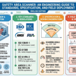
| Standards context | ESPE per IEC 61496-1:2020; control reliability per ISO 13849-1:2023 |
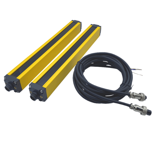
Safety Light Curtain Wiring Basics: What the OSSD Outputs Do
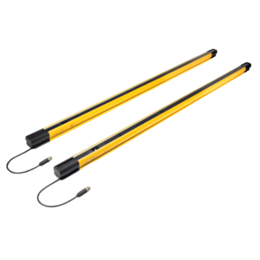
A OSSD is a self-monitoring solid-state output. A Type 4 safety light curtain has two of them, and they switch together: when the protected field is clear, both sit at 24V; when a finger, hand, or body breaks a beam, both drop to 0V. That dual output is the entire point. A single contact could weld closed, or a single wire could short to 24V and never tell you it failed. Two independently switched, constantly cross-checked outputs allow the receiving device to detect a stuck channel because the two signals stop matching, and that diagnostic coverage is what allows the wiring to reach a high safety rating rather than just “usually works.”
One rule of any safety light curtain wiring diagram follows from that: each OSSD goes to its own input. Never jumper OSSD1 and OSSD2 together to save a terminal. The moment you merge them you throw away the diagnostic coverage that the dual-channel design exists to provide, and you limit the achievable Performance Level regardless of how good the curtain is.
💡 Pro Tip
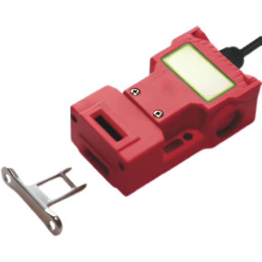
Wire colors are not universal, but a common standard is brown = +24V, blue = 0V, and other two colors for OSSD1 and OSSD2. Double check against the individual pinout diagram before you land one single wire – a mislanded OSSD reads as a permanent fault, not a wiring “almost.”
OSSD Output Types: PNP vs NPN and Reading the Test Pulses
Prior to a diagram mattering, the output logic does. Most modern safety light curtains use PNP (sourcing) outputs: the OSSD switches the +24V supply to the input, and the input shares the 0V reference. Older or region-specific models use NPN (sinking) outputs that switch to 0V. Mixing them is the quickest path to a curtain that “does nothing” or faults instantly, because the receiving input never sees the voltage variation it expects.
What is the difference between NPN and PNP OSSD outputs?
A PNP output sources current – in the ON state it connects the load to +24V, so the input go high when the field is clear. An NPN output sinks current – in the ON state it pulls the load to 0V. Its practical consequence is the common reference: a PNP curtain expects the input module to share its 0V (negative) rail, while an NPN curtain expects a shared +24V rail. Safety inputs on relays and sourcing PLCs are overwhelmingly built for PNP devices, which is why PNP has become the default. If your curtain is NPN and your safety input is PNP, you need a different curtain or a signal converter, not a wiring trick.
| Property | PNP (sourcing) | NPN (sinking) |
|---|---|---|
| ON state switches | +24 V to the input | 0 V to the input |
| Shared reference | 0 V (negative) | +24 V (positive) |
| Typical use today | Default for safety inputs | Legacy / specific regions |
| Test pulse direction | Brief drop toward 0 V | Brief rise toward 24 V |
Now the detail almost every wiring guide skips: test pulses. Each OSSD periodically forces its line to the opposite state for a very short time to prove it can still switch and to check for shorts between channels. Pulse width is short – somewhere around 200s on some curtains and a few milliseconds on others – and the period is typically a couple hundred milliseconds. These pulses are normal and a safety-rated input expects them. A standard digital input usually doesn’t, and that single fact drive most of the connection problems later in this guide.
Wiring a Light Curtain to a Safety Relay (Guardmaster, PNOZ)
By far the most common termination is a dedicated safety relay – an Allen-Bradley Guardmaster unit such as a 440R, or a Pilz PNOZ. The relay takes the two OSSDs on dual-channel safe inputs, monitors them for agreement, watches the final switching devices through an EDM loop, and drops its safety outputs the instant either OSSD opens. If you haven’t chosen a unit yet, our guide to safety relay modules covers the families and ratings.
On a typical PNOZ-style relay the terminal map is consistent enough to plan from: channel1 lands on S11/S12, channel2 on S21/S22, and the reset circuit on S33/S34. OSSD1 connects to the channel-1 input, OSSD2 to channel-2, the curtain shares the relay’s 0V, and the EDM (External Device Monitoring) loop runs the normally-closed auxiliary contacts of your downstream contactors K1 and K2 back into the relay so it can confirm they actually dropped out.
| Curtain signal | Typical relay terminal | Purpose |
|---|---|---|
| +24 V (brown) | A1 | Logic supply (non-pulsed) |
| OSSD1 | S11 / S12 | Safe input channel 1 |
| OSSD2 | S21 / S22 | Safe input channel 2 |
| Reset button | S33 / S34 | Manual reset / restart |
| EDM feedback | In the reset loop | NC aux of K1/K2 |
One field point worth more than any diagram: power the curtain from a clean, non-pulsed 24V supply – the same rail you would land on the relay’s A1, not a test-pulse output from another device. Field technicians regularly report curtains that fault intermittently because they were powered from a pulsed source, and the curtain’s own monitoring reads the borrowed pulses as a fault.
Connecting OSSD Outputs to Allen-Bradley GuardLogix
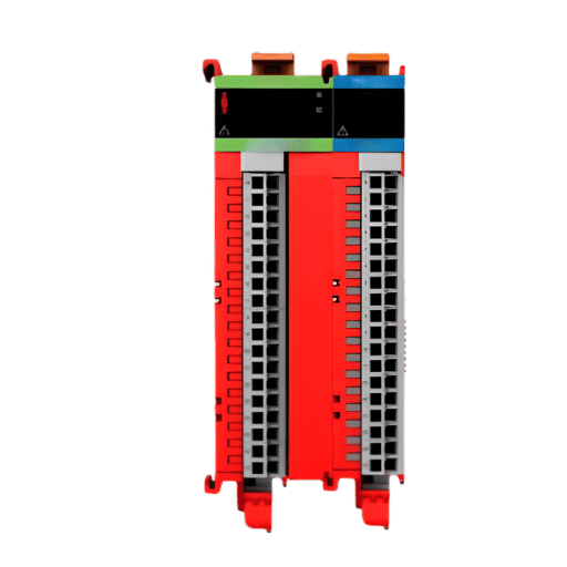
This is where most published diagrams go quiet. Unlike a small safety relay, a GuardLogix controller doesn’t have safe inputs on its chassis – the OSSDs land on a CIPSafety I/O module, most commonly a GuardI/O block such as a 1791ES on EtherNet/IP, and the safety logic runs in the controller’s safety task in Studio 5000.
Can you connect a safety light curtain directly to GuardLogix?
Not to the controller itself, but to the safety I/O on the controller – and that’s the clean way to do it. You would connect OSSD1 and OSSD2 into two safe inputs on the GuardLogix safety I/O (the Guard I/O in our case), then configure those two points as a dual-channel equivalent in the safe I/O configuration, and the controller sees them as a single monitored input. You then Map that safe input tag to your safe routine. You’ve got no separate safety relay in that path, the GuardLogix safety I/O and GuardLogix safety task provides safety function. What happens is a common alternative is to take the two OSSDs to a little safety relay, then a relay to a standard GuardLogix input, but there’s just unnecessary hardware that way, and another failure point where none is needed, since the controller sees the curtain data already.
The two bits of configuration data to make this work the first time: first is to tell the safe inputs not to apply their own test pulses on these points (the OSSD already does its own pulse test – a generated pulse is fighting it, resulting in spurious trip calls), and second, to set a meaningful discrepancy time (the amount of window between channel disagreement for it to declare a trip). It’s near instantaneous when the curtain blocks OSSD1 and OSSD2, so all you’re trying to do is avoid noise; set too tight and you get bogus trips, set too wide, and you reduce fault coverage.
With an OSSD device, “the controller input must not generate its own test pulse on that line – the output already pulse tests itself and generating another pulse just makes for a trip” says the technician and engineer in charge of commissioning safety devices. For the light curtain channels, this translates to”setting the safe input not to use test pulses.”
Connecting OSSD Outputs to a Siemens SIMATIC Fail-Safe PLC
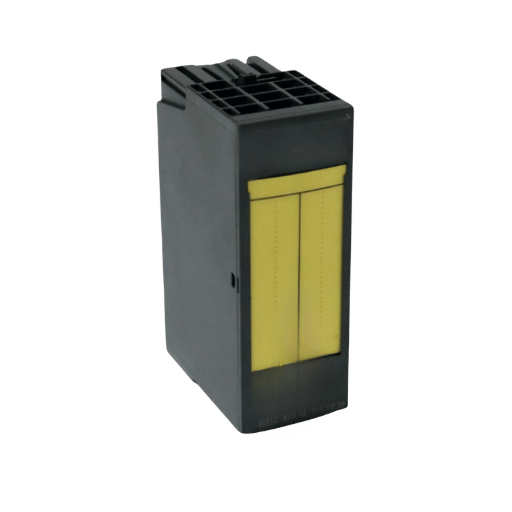
Siemens hardware logic works along these lines, with a few naming change. You would again wire OSSD1 and OSSD2 into a pair of fail-safe digital inputs (on an ET200SP F-DI module, or directly on an S7-1500F) and set those two points for 1oo2 evaluation on the fail-safe’s safe settings in TIA Portal. The Siemens channel where the data resides has a PROFIsafe address, and the safety program uses the output of the safe signals.
One of the points that often causes confusion on Siemens hardware concerns power supplies for the sensors. The fail-safe input can power your sensor using its own internal test pulses, or you can configure it to use an external supply. Since a light curtain already has its own power and performs its own pulse test to its OSSDs, the Siemens F-DI will be configured to use an external supply, leaving the OSSD to handle its own testing. Connect OSSD1 and OSSD2 to your fail-safe inputs, tell them that they’ll be supplied by an external power source, group them together as a 1oo2 group, and proceed with your safety routine design.
⚠️ Important
Either way – you program GuardLogix, or you program Siemens – don’t leave the safe input’s test pulses enabled with OSSD inputs; both platforms expect the manufacturer’s product to perform its own safety pulse tests. Do that one thing and most so-called “random” trips will disappear.
EDM, Reset, and Restart Interlock: The Details That Trip People Up
EDM is separate from the reset and EDM isseparatefrom restart interlock. EDM is the monitoring of the last few switching stages: When EDM is implemented the relay and the PLC look at the normally-closed aux contacts on the contactors commanded by that relay/PLC; so when one contacts Weld the feedback loop won’t be completed and won’t let you reset. Missing EDM wiring or mis-wired EDM is the Number 1 “It won’t reset.”call we get in.
Safety Reset vs Auto-Reset Auto-reset versus Safeven-there’s really a lot more safety then convenience being considered. A manual reset can only re-engage the machine once it sees the light curtain clear AND an operator take deliberate action to reengage it. You must also use manual reset if an operator can get into the light curtain protected area without being visible from their normal operator’s station-i.e., the light curtain is serving as access guard. If auto-reset has been wired in on an access application, it’s generally a significant mistake.
📐 Engineering Note
As per the start and reset functions found in ISO 13849-1:2023, an “enterable” guard must incorporate a manual reset wired so that the reset device is located such that the entire hazard zone is in view and the reset signal is generated when the reset button is released (falling edge), not while it is pressed. Reset to S33/S34 (or the controller’s reset input) and put the EDM feedback in series in this monitored circuit to prevent a welded contactor.
Common Light Curtain Wiring Faults and How to Diagnose Them
Self-monitored curtain types never simply give up the ghost – they’ll become locked and show up on a code reading. What’s needed is interpreting what problem lies behind the code, on a wiring system. Most troubleshooting time is chewed up with the causes highlighted below.
| Symptom | Likely cause | Fix |
|---|---|---|
| Random trips on a PLC input | Standard input misreads OSSD test pulses as OFF | Use a safe input; or add input filtering / an RC network |
| Instant OSSD lockout | OSSD shorted to 24 V, to 0 V, or to the other channel | Ohm out each OSSD to ground and to its partner |
| Channel discrepancy fault | Worn interposing relay adds timing skew between channels | Remove the mechanical relay; wire OSSDs to safe inputs directly |
| Faults on long cable runs | Voltage drop / capacitance degrades pulse integrity | Keep ≥21 V at terminals; shorten run; use proper gauge |
| Won’t reset | Open or missing EDM feedback loop | Verify NC aux contacts of K1/K2 in the reset loop |
That top row is important because that’s the one that the engineers have to tussle with on a repeated basis, as there’s none of the Input Conditioning found in a safe input that the normal PLC input have, thus it’s reading all of the OSSD test pulse input as OFF for a momentary, which makes the machine jerk. As should be readily apparent, an OSSD belongs on a Safe Input! Now, If you need a parallel, non-safe input (to monitor with for diagnostics only, not for the safety function!), then use filtering or an RC circuit and just don’t hook up the main safety stop to the non-safe one. This is also where muting a safety light curtain, and muting lights begin to add their own wiring as their input devices take up an extra pair of terminals, and these too must be read and watched.
Safety Relay vs Safety PLC: Choosing the Right Termination
And where this wiring is heading will make the cut for me: bring the curtain into a safety relay (which should be standalone) or in an safety PLC. A fair golden rule here’s that when safety function is short and hardwired, use the relay, and when it’s long or should possibly get modified use a PLC.
✔ Safety relay fits when
- One or two safety devices, one zone
- Logic is fixed and unlikely to change
- Lowest hardware cost, fastest commissioning
- No need for diagnostics over a network
⚠ Safety PLC fits when
- Multiple zones, curtains, or muting
- Logic will evolve with the machine
- We need fault information from the network
- Cascaded or coordinated stops
Decision shortcut
- O perdea, o oprire, fără muting safety relay (440R / PNOZ).
- Two or more device one location with logic is steady safety relay multi-function switch and input devices
- Multiple zones, muting, or future expansion GuardLogix or Siemens fail-safe PLC.
- The curtain shouldn’t just be “a relay pass through” to a safety PLC; just make the PLC the input instead of the relay. It just adds cost without adding any safety.
Wiring for Category 4 / PLe Compliance
And this is the new mental model for what’s listed above: The curtain doesn’t ‘own’ the safety rating-the architecture does.
An integrated safe photo-electric light curtain is rated ‘electro-sensitive protective equipment’ under the guidance of IEC 61496-1:2020, but that rating applies to the sensing function itself. The Performance Level of the entire safety function-sensing, controlling, and turning off the hazard-is the Performance Level (PL) achieved when wiring and monitoring the complete system under ISO 13849-1.
This is why dual-channel is so important. This feature-a dual or separate wiring path-or the equivalent from another vendor, is what’s required for a two-OSSD (one relay in, another out of the unsafe zone) safety circuit to achieve PLe / Category 4. Connect both OSSD channels, bypass the second EDM, or wire the curtain output to one ordinary relay output, and your architecture drops from Category 4 to whatever level your monitoring supports.
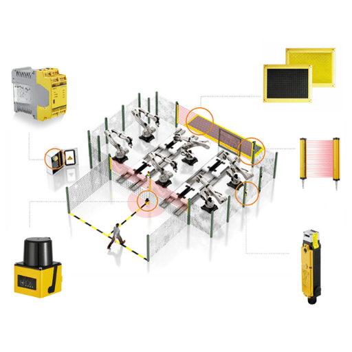
EN 954-1 history correlates with Type classes, and modern systems assess achieved performance level through the architecture. For the broader picture of where curtains sit among safeguards, see machine guarding with light curtains, and in the United States, review OSHA’s presence-sensing device guidance for the regulatory baseline.
The OSSD Termination Matrix
Before you finalize your next machine, review this basic architecture check chart. It reviews possible configurations of wiring termination at the safety system for OSSD test pulses, monitoring (both channels), and the highest safe PL you can obtain.
| Termination | Dual-channel monitored? | Tolerates OSSD test pulses? | Achievable rating |
|---|---|---|---|
| Standard PLC input | No | No — misreads pulses | None (not a safety function) |
| Safety relay (440R / PNOZ) | Yes | Yes | Up to Cat 4 / PLe |
| GuardLogix Guard I/O (1791ES) | Yes (configured pair) | Yes (disable input pulsing) | Up to Cat 4 / PLe |
| Siemens F-DI (1oo2, ext. supply) | Yes (1oo2) | Yes (external supply) | Up to Cat 4 / PLe |
Industry Outlook: Where Light Curtain Integration Is Heading
Two broad forces will reshape the way you look at these charts in the near future. For one, the standards themselves continue to evolve. The fourth edition of ISO 13849-1:2023, released in April 2023, supersedes the 2015 version and consolidates into a single standard material formerly scattered in separate validation guides.
For machines built over the next few years during the overlapping application periods for these standards, verify that your 2026 project validation documentation specifies the correct standard and align your wiring architecture justification to that standard.
Architecture is the second force influencing how you’ll wire your machine is architectural in nature. Widespread adoption of safe integrated controls, the simplification of multiple control channels with networks like CIP Safety and PROFIsafe, and the growing importance of IO-Link Safety for device-level diagnostics, are all reducing reliance on individual safety relays. When considering wiring for a multi-machine setup in 2026, especially for any possibility of expansion, plan around a fail-safe PLC with safe network I/O rather than the single-wire, relay-logic approach which will soon seem hopelessly outdated. For multi-zone cells, our guide to Type 4 safety light curtain selection pairs well with this wiring guide.
Frequently Asked Questions
Q: Can I connect OSSD outputs to a normal (non-safety) PLC input?
View Answer
Not for the safety function. A standard input lacks the conditioning a safe input has, so it reads the OSSD’s normal test pulses as momentary OFF signals and the machine trips at random. The safety stop must go through a safe input on a safety relay or fail-safe PLC. You can mirror the state to a standard input for diagnostics only, with proper filtering, but it can never be the thing that stops the hazard.
Q: Do I still need a safety relay if my PLC is a GuardLogix?
View Answer
No. Wire the OSSDs to a Guard I/O safety input module and let the GuardLogix safety task handle the logic. Adding a safety relay just to pass a contact into the controller adds hardware and a failure point without improving the safety rating.
Q: What wire gauge and maximum cable length should I use for OSSD signals?
View Answer
Follow the curtain datasheet, but the governing limit is keeping at least about 21 V at the device terminals under load and preserving the test-pulse shape. Long runs add voltage drop and capacitance that can degrade the pulses and cause faults, so size the conductors generously and keep the run as short as practical, using shielded cable grounded at one point.
Q: Why are there two OSSD outputs instead of one?
View Answer
Redundancy with diagnostics. Two independently switched, cross-monitored outputs let the receiving device detect a single fault — a stuck output or a short — because the channels stop agreeing. That single-fault tolerance is what allows the wired safety function to reach Category 4 / PLe.
Q: Can I wire two light curtains to one safety relay?
View Answer
Sometimes, but it is usually the signal to move to a safety PLC. A few relays accept multiple dual-channel inputs, yet once you have two curtains, separate zones, or muting, a fail-safe PLC gives cleaner logic and per-device diagnostics that a relay cannot.
Q: Does PNP or NPN affect the achievable safety rating?
View Answer
No — the rating comes from the dual-channel architecture and monitoring, not the output polarity. What PNP vs NPN affects is compatibility: the curtain’s output type must match what the safe input expects, or the connection simply will not work.
Specifying a safety light curtain for your machine?
QJKH makes the Type 2 and Type 4 safety light curtains that cleanly integrate to the Guardmaster, PNOZ, GuardLogix, and Siemens fail-safe lines of controls. Before cutting a single wire, select the device that meet your required resolution, range, and output.
Explore QJKH safety light curtains →
Ask an engineer a wiring question
Why We Wrote This Guide
Most on-line safety light curtain wiring diagram guides do not even get to the safety relay point. Even fewer include the ossd-to-GuardLogix or ossd-to-Siemens circuit. If any do mention the circuit, they often omit the one specific test-pulse setting that causes the majority of all nuisance trips. In an effort to avoid these pitfalls, this guide was designed with a focus on what is actually necessary, backed up solely by the underlying applicable standards (OSHA, ISO 13849-1:2023, and IEC 61496-1:2020) rather than brand specifications. Always verify all safety circuits with the device manuals and the relevant machine standards.
References & Sources
- 29 CFR 1910.217, Mechanical Power PressesU.S. Occupational Safety and Health Administration
- Machine Guarding eTool: Presence Sensing DevicesU.S. Occupational Safety and Health Administration
- Standard Interpretation: Presence Sensing Device Initiation and MutingU.S. Occupational Safety and Health Administration
- ISO 13849-1:2023, Safety of machinery, safety-related parts of control systemsInternational Organization for Standardization
- IEC 61496-1:2020, Electro-sensitive protective equipment, general requirementsInternational Electrotechnical Commission
- Electro-sensitive protective equipment and its relationship to SIL/PLIFA (DGUV)