Get in touch with QJKH Company
LiDAR Anti-Collision System for Overhead Cranes — Industrial Sensor Solutions
Prevent Overhead Crane Collisions with Industrial LiDAR – 3mm Accuracy, 0.2-200m Range. Zone deceleration and emergency stop protection for bridge cranes, gantry cranes, multi-crane runways.
Request a Quote
Why Overhead Cranes Need LiDAR Anti-Collision Systems
An anti collision system for cranes is not a theoretical safeguard — it is a direct response to documented fatalities and enforcement actions that cost facilities millions each year. Overhead crane collisions between adjacent bridges, between a crane and end-stop buffers, or between a crane and fixed structures account for a substantial portion of the 42 to 44 crane-related fatalities counted annually in the United States. A 10-year survey of 70 major crane incidents by Konecranes placed total financial damage above $500 million, combining equipment repair, factory downtime, injury litigation, and regulatory penalties.
Enforcement consequences compound the problem. A Crane Training Universities registry documents 249 overhead crane incidents that triggered 838 OSHA violations in a single review period — over 3.4 violations per event. CICB data shows roughly 90% of crane accidents trace back to human error: misjudged clearances, blocked sightlines, operator fatigue, and communication failures during tandem lifts. Conventional proximity warning devices — bumpers and limit switches — actuate only after contact has begun. They do not gauge distance. They do not decelerate.
LiDAR-based anti-collision systems address this root failure mode: insufficient spatial awareness. A time-of-flight LiDAR sensor mounted on the crane bridge continuously measures distance to adjacent cranes, end-stop structures, and fixed obstacles. When measured separation falls below a configured warning threshold — set at 5 to 15 meters depending on travel speed — it signals the crane’s variable-frequency drive (VFD) to begin staged deceleration. If the crane continues to approach and enters the emergency zone — 1 to 3 meters — the system triggers a hard stop through the safety relay circuit. This four-stage collision avoidance sequence (monitor → warn → decelerate → stop) reacts in under 100 milliseconds, faster than any human operator.
How LiDAR Zone Protection Works
Each sensor establishes concentric distance zones around the crane. Zone 1 (normal operation) allows full speed. Zone 2 (pre-warning) activates a visual/audible alert. Zone 3 (deceleration) sends an analog signal to the VFD, proportionally reducing crane speed. Zone 4 (emergency stop) opens the safety relay. All zone boundaries are configurable through the sensor’s RS485 or Ethernet interface, allowing adjustments for different runway lengths and operational patterns without physical rewiring.
For facilities operating multiple cranes on a shared runway – the most common crane-to-crane collision scenario – LiDAR delivers a critical advantage over contact-based systems: it measures the closing distance between two moving objects simultaneously. Both cranes receive deceleration commands based on their relative closing speed, not just their absolute position.
CCH LiDAR Anti-Collision Sensors — Models & Selection Guide
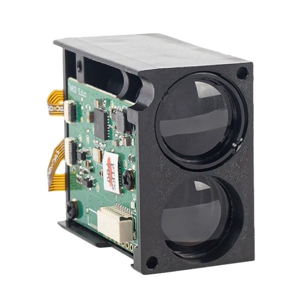
CCH produces three levels of LiDAR anti-collision sensor, each suited to its own operating envelope. The correct model to fit can be determined by four factors: runway length, number of additional cranes on the same runway, environment (indoor or outdoor, dusty or not dusty), and interface compatibility to the crane control system.
Short Range
CCH-LR30 Series
Single runway applications, indoor environments
- Range: 0.2 – 30 m
- Accuracy: ±3 mm
- IP Rating: IP65
- Temp: -10°C to +50°C
- Output: 4–20 mA / NPN/PNP
- Interface: RS485
- Power: 12–24 VDC
A great choice for: single-bridge cranes found in manufacturing cells, machine shops and assembly lines where runway spans are less than 30 meters.
Most Selected
Mid Range
CCH-LR100 Series
Multi-crane coordination, standard industrial
- Range: 0.2 – 100 m
- Accuracy: ±3 mm
- IP Rating: IP67
- Temp: -25°C to +60°C
- Output: 4–20 mA / RS485
- Interface: RS485 + Ethernet
- Power: 12–24 VDC
Good for: two and three crane runways in steel mills, automotive plants and fabrication shops where it is critical to measure crane-to-crane distance.
Long Range
CCH-LR200 Series
Port, outdoor, and large-span applications
- Range: 0.2 – 200 m
- Accuracy: ±5 mm
- IP Rating: IP67
- Temp: -30°C to +65°C
- Output: 4–20 mA / RS485
- Interface: RS485 + Ethernet + Modbus
- Power: 12–24 VDC
Mid temperature range: suitable for: port gantry cranes, shipyard overhead travelling cranes, very long span warehouse systems, out door applications exposed to rain, salty air and severe temperature variations.
Complete Specification Comparison
| Parameter | CCH-LR30 | CCH-LR100 | CCH-LR200 |
|---|---|---|---|
| Detection Range | 0.2 – 30 m | 0.2 – 100 m | 0.2 – 200 m |
| Accuracy | ±3 mm | ±3 mm | ±5 mm |
| Repeatability | ±1 mm | ±1 mm | ±2 mm |
| IP Rating | IP65 | IP67 | IP67 |
| Operating Temp. | -10°C to +50°C | -25°C to +60°C | -30°C to +65°C |
| Analog Output | 4–20 mA | 4–20 mA | 4–20 mA |
| Digital Interface | RS485 | RS485 + Ethernet | RS485 + Ethernet + Modbus |
| Switching Output | 2× NPN/PNP | 2× NPN/PNP | 2× NPN/PNP |
| Power Supply | 12–24 VDC | 12–24 VDC | 12–24 VDC |
| Response Time | ≤50 ms | ≤50 ms | ≤80 ms |
| Laser Class | Class 1 (eye-safe) | Class 1 (eye-safe) | Class 1 (eye-safe) |
Application-Based Decision Matrix
| Application Scenario | Recommended Model | Key Requirement | Typical Qty per Crane |
|---|---|---|---|
| Single crane, indoor, runway <30 m | CCH-LR30 | End-stop collision prevention | 2 sensors |
| 2–3 cranes, shared runway, indoor | CCH-LR100 | Crane-to-crane distance control | 2–4 sensors |
| Multi-crane, outdoor or semi-outdoor | CCH-LR200 | Weather resistance + long span | 2–4 sensors |
| High-dust (foundry, cement, mining) | CCH-LR100 + air purge | IP67 + optical window protection | 2–4 sensors |
| Port gantry / ship-to-shore crane | CCH-LR200 | 200 m range + salt air resistance | 4–6 sensors |
“In a multi-crane runway situation, the most important design consideration is the deceleration distance, i.e., the physical distance in which a heavy bridge crane can be brought from travel speed back to a complete rest. Our LR100 series provides this measurement at 3 mm – the control system has enough resolution to generate a deceleration curve that can be both load smooth and safe to other equipment.”
LiDAR vs Laser vs Ultrasonic — Overhead Crane Sensor Technology Comparison
Choosing the appropriate sensor technology for an overhead crane collision avoidance system needs quantitative, not qualitative, performance data. The following 7-dimension comparison uses published specification and known field performance data to compare laser distance sensors, ultrasonic sensors, radar, and LiDAR under real crane operating conditions:
| Performance Dimension | LiDAR (ToF) | Laser Distance | Ultrasonic | Radar (mmWave) |
|---|---|---|---|---|
| Detection Range | 0.2 – 200 m | 0.1 – 150 m | 0.3 – 10 m | 0.5 – 80 m |
| Accuracy | ±3 mm at 100 m | ±1 mm at 50 m | ±5 mm at 5 m | ±10 mm at 30 m |
| Dust/Debris Resistance | Moderate — operates through light to medium dust with air purge accessory; heavy particulate reduces range by 20–40% | Low — visible laser beam scattered by airborne particles; unreliable above 5 mg/m³ dust concentration | High — acoustic signal unaffected by optical obstructions | High — mmWave penetrates dust, smoke, and light rain |
| Multi-Target Detection | Yes — scanning LiDAR detects multiple objects per sweep; ranging LiDAR reports first return | No — single point measurement only | No — single-axis cone detection | Limited — 2–3 targets with signal processing |
| Ambient Light Immunity | 905 nm wavelength — immune to visible light including welding arc; direct sunlight reduces max range by 10–15% | Visible red laser affected by ambient light above 40,000 lux; infrared models perform better | Fully immune — acoustic principle unaffected by light | Fully immune — RF signal unaffected by light |
| Installation Complexity | Medium — requires mounting bracket, power, and one digital bus connection; alignment to beam centerline within ±2° | Low — compact housing, simple point-and-mount; requires reflective target at far end | Low — compact, self-contained; limited range constrains placement options | Medium — antenna positioning critical for beam width; requires careful avoidance of metallic reflections |
| Typical Cost Per Sensor | $400 – $2,500 depending on range and interface | $200 – $1,500 | $80 – $400 | $600 – $3,000 |
LiDAR wins outright for overhead crane anti-collision where the runway exceeds 10 m, multiple cranes share a common rail, or where the sensor must deliver millimeter-accuracy data to a PLC or VFD for speed-proportional deceleration. Long range, high accuracy, and digital interface support (RS485, Ethernet, Modbus) give LiDAR a decisive control integration edge — sensor output maps directly onto deceleration curves without the signal conditioning required by analog-only sensors. Ultrasonic remains a viable and lower-cost option for short-range end-stop protection in clean environments, but its 10 m ceiling and ±5 mm accuracy make it unsuitable for crane-to-crane coordination on shared runways. With 10mm accuracy and maximum sensing range of 10 m, ultrasonic sensors are a poor choice for crane-to-crane positioning on shared runways. Radar performs comfortably in the dustiest and fiercest of weather conditions, but energy distribution limitations (10m accuracy at all points of intersection) turn its long-term utility into a secondary nature. Laser distance sensors have the highest single-point accuracy of any type (1mm) but require a cooperative reflective target, an installation restriction that can be a point of failure in the vibration-prone crane environment. For virtually all overhead crane anti-collision applications, LiDAR offers optimal balance of operating range, accuracy, environmental immunity and control system versatility.
Interested in seeing how CCH LiDAR stacks up for your application?
Request a Custom ComparisonReal-World Results — How LiDAR Reduces Crane Downtime & Costs
Cost justification for a crane safety system rests on three documented cost elements: collision repair costs, lost production due to idling, and regulatory violations. The following four documented application scenarios demonstrate how each applies to the eight environments.
1. Steel & Metal Fabrication — Multi-Bridge Crane Coordination
Steel service centers and fabrication shops run 2 to 4 bridge cranes on a shared 60–100 meter runway. Crane-to-crane contact during simultaneous material handling — particularly when both cranes serve the same cutting or welding station — is the primary collision risk. LiDAR sensors mounted on opposing ends of each bridge measure inter-crane distance in real time. With graduated zone protection, the system reduces travel speed proportionally as cranes approach each other, eliminating hard-stop jolts that damage loads and crane structures. Facilities in this category report that a single bridge crane collision event generates $15,000 to $40,000 in structural repair costs and 2 to 5 days of runway downtime.
2. Automotive Manufacturing — High-Precision Positioning
Automotive die and stamp assembly factories demand aisle capacity for cranes to transfer dies and sub-assemblies with minuscule clearances: often < 50 mm to the neighboring equipment. Users of LiDAR in this situation report a dual-use need: for collision protection, and in conjunction with slow approach controls, for autoalignment in the absence of visual reference. Automotive press die change-out applications where a 25 ton die must be lowered through an aperture measuring 50 mm by 50 mm between guiding rails uses a laser sensor with 3 mm accuracy to prevent range-related equipment damage of $50,000 per incident.
3. Port & Logistics — Long-Range Outdoor Harsh Environment
Container ports and intermodal facilities operate gantry cranes on runways exceeding 150 meters, exposed to wind, rain, salt air, and temperature swings from -20°C to +50°C. CCH’s LR200 series, rated IP67 with an operating range down to -30°C, handles these conditions. Port crane collisions carry outsized financial consequences: a single gantry crane structural repair event can exceed $100,000, with berth downtime costing $50,000 to $200,000 per day in delayed vessel operations. LiDAR’s 200-meter detection range provides the early warning distance needed for high-inertia gantry cranes that require 30+ meters of deceleration distance at full travel speed.
4. Warehouse & Distribution — Automated Zone Management
Modern distribution centers increasingly deploy automated or semi-automated overhead cranes for pallet handling and order staging. In these installations, LiDAR anti-collision sensors integrate with the warehouse management system (WMS) through Ethernet or Modbus, providing real-time crane position data that enables dynamic zone allocation. Rather than fixed mechanical stops, the system creates software-defined zones that adjust based on operational priority — allowing cranes to operate closer together during peak throughput periods while maintaining safety margins. This approach increases effective runway utilization by 15–25% compared to fixed-zone systems.
Investment Recovery Framework
Building a business case for crane anti-collision systems starts with documented incident cost data:
Collision Repair Cost
$10K – $50K
per incident — structural, electrical, mechanical
Production Downtime
$5K – $20K/day
lost output during crane repair period
OSHA Penalty
$16,131
per violation — high gravity assessment
A complete LiDAR anti-collision system — sensors, mounting hardware, wiring, and commissioning — represents an investment of $2,000 to $10,000 depending on sensor count, detection range, and integration complexity. Based on industry incident data, facilities recover their investment within the first avoided collision event. For multi-crane runways where collision probability peaks, payback is measured in months, not years.
Safety Certifications & Compliance Standards
Every crane anti-collision device installed in a regulated facility must carry verified certification. CCH LiDAR sensors ship with these credentials:
CE Marked
European Conformity — electromagnetic compatibility and safety directives verified
FCC Certified
US Federal Communications Commission — RF emissions compliance for 905 nm laser
RoHS Compliant
Restriction of Hazardous Substances — lead-free manufacturing verified
ISO 9001:2015
Quality Management System — Hangzhou factory audited and certified
Applicable Industry Standards
| Standard | Jurisdiction | Relevance to Anti-Collision |
|---|---|---|
| OSHA 29 CFR 1910.179 | United States | Requires overhead and gantry cranes to have devices preventing trolley and bridge travel beyond safe limits. LiDAR anti-collision sensors directly satisfy the proximity protection requirement. |
| ASME B30.2-2022 | United States | Specifies anti-collision devices for cranes operating on shared runways. Section 2-3.4 addresses clearance requirements between adjacent cranes and between cranes and fixed structures. |
| CMAA Specification #70 | United States | Crane Manufacturers Association of America specification for top-running bridge and gantry type multiple girder electric overhead traveling cranes. References anti-collision as a required safety feature for multi-crane installations. |
| EN 15011:2020 | European Union | European standard for overhead travelling cranes. Specifies performance requirements for buffer and anti-collision systems, including sensor-based proximity detection. |
OSHA Penalty Context:
High gravity violations under OSHA’s current penalty schedule are assessed at $16,131 per occurrence. Willful or repeated violations reach $161,323 per occurrence. A single crane incident that triggers multiple violation citations — the documented average is 3.4 violations per incident — generates cumulative fines of $55,000 or more before accounting for any injury or fatality consequences.
Procurement Guide — Pricing, Lead Time & OEM Support
Procuring industrial sensors from Chinese sources can require a formal evaluation process, starting with the project planning stage. This section lays out the framework for budget development, supplier investigation, and ongoing support evaluationto support procurement managers and engineering directors selecting a first-time or second-time source.
Pricing Factors — What Drives the Cost of a LiDAR Anti-Collision System
Total cost of ownership for project specific sensor quotations stems from an interaction of five interrelated factors. awareness of the interaction of these factors helps procurement departments formulate an accurate project budget before requesting a quotation:
Factor 1: Detection Range
Detection range from 100 m+ and must have a laser emitter with significant power and a highly sensitive photodetector all index upword cost of each sensor. Select the lowest cost sensor that still meets your detection range and speed application requirements.
Factor 2: IP Rating and Environmental Protection
IP65 (indoor, dust-based) rated sensors prices will be less than IP67 (submersible, heavy washdown) rated sensors. Traveling cranes in a indoor dry environment will benefit from selecting a IP65 rated sensor in budget. Applications that include outdoor, port, or foundry require fully sealed IP67 rated units the extra cost is related to corrosion resistant housings and . wider temperature tolerance components.
Factor 3: Number of Sensors per Crane
A 2 sensor position control for the end stops on a single crane. 2 to 4 sensors are required for a 2-crane shared runway that employs end stops and center crane protection. 4 to 6 sensors per crane are needed on multi-crane runways with 3 or more bridges. Price break for high quantity purchasing may apply.
Factor 4: Integration Interface
Basic analog output (4–20 mA) and discrete switching (NPN/PNP) implementations cost considerably less than Ethernet/IP, MODBUS TCP or PROFINET setups. Digital communication modules add per-channel sensor cost but eliminate the external signal converters that PLC-based crane control systems otherwise require.
Factor 5: Certification and Compliance Costs
Standard CE/FCC certification is included. Customers requiring additional third-party testing reports, country-specific certifications, or full material traceability records may incur extra preparation fees.
Contact CCH with the specifications of the application for a quotation. Provide: Runway length, No. of cranes, indoor/outdoor, existing control system type (PLC brand + model if available), delivery location.
Supplier Verification — How to Evaluate a Chinese Sensor Manufacturer
Industrial safety sensors sourced from China by procurement teams should follow a 4 step due diligence process:
Step 1 – Factory Audit
Get a virtual or real-time factory tour from the supplier. CCH operates a fully certified state-of-the-art manufacturing facility located at Hangzhou Airport Economic Demonstration Zone – a government-controlled industrial park with certified third party quality control. Verify dedicated SMT lines, optical assembly clean rooms, and in-house environmental testing chambers (thermal cycling, vibration, IP ingress).
Step 2 – Sample Testing
Order 1-3 evaluation units before full-rate order. Field test the installation with the real operating conditions – on the crane, in the dust, at the minimum and maximum temperatures, with the maximum truckcycle vibration profile you can. CCH provides evaluation units with technical support.
Step 3 – Certification verification
Request copies of CE, FCC and RoHS certificates and validate them. For CE markings make sure the Notified Body number in the certificate matches the table of valid EU-USAS Recognized Bodies. CCH provides all certification documents with traceable test report references.
Step 4 – references check
Ask the supplier to provide 2-3 references from the same industry vertical. Make a call to those references to verify delivery reliability, product failure rates and support response times.
OEM Customization
CCH is open to OEM-ing or private labelling for crane OEMs, system integrators, and safety equipment distributors. Available customizations: custom color housing, branded enclosure, changed cable length and connection types, changed communication protocols, changed application firmware settings. OEM minimum order quantity depends on project – consult with CCH sales engineer.
After-Sales Support
All CCH LiDAR sensors are sold with 24-month standard warranty, remote technical support (video+email) in English and Mandarin, firmware upgrade access, replacement parts guaranteed available for 7 years. Extended warranty, onsite commissioning are optional extras.
Crane Anti-Collision Sensor Selection Tool
Answer 3 questions to find the right LiDAR sensor for your crane system
Crane Setup
Tell us about your overhead crane installation
Environment
Operating conditions affect sensor rating and optics selection
Integration
Match the sensor output to your control system
Your Recommended Sensor
Based on your crane setup, environment, and integration requirements
FAQ — Overhead Crane Anti-Collision Systems
An anti-collision system on a crane is an electronic safety system that continuously measures distance between the crane and nearby objects — other cranes on the same runway, end-stop structures, building columns, or fixed equipment. It uses sensors (LiDAR, laser, ultrasonic, or radar) to detect when the crane enters a pre-defined danger zone. When distance falls below the warning threshold, the system issues graded responses: first an audible/visual alarm, then a signal to reduce travel speed, and finally a hard emergency stop if minimum safe distance is breached. Modern LiDAR-based systems deliver this four-stage response sequence in under 100 milliseconds.
A LiDAR anti-collision system emits short pulses of infrared laser light (905 nm wavelength, Class 1 eye-safe) toward potential obstacles. It measures the time each pulse takes to reflect back — this time-of-flight measurement converts directly to distance with ±3 mm accuracy. Hundreds of measurements per second provide a continuous distance reading to the crane’s control system. A PLC or dedicated safety controller compares the measured distance against configurable zone thresholds and issues the appropriate speed-reduction or stop command through relay outputs or digital bus communication.
Four stages define the sequence: (1) Monitoring — the sensor continuously measures distance during normal crane operation at full travel speed; (2) Pre-Warning — when the crane enters the outer warning zone (10–15 m), the system activates a visual beacon and audible alarm; (3) Controlled Deceleration — when the crane enters the deceleration zone (3–10 m), it sends a proportional signal to the variable-frequency drive, gradually reducing travel speed; (4) Emergency Stop — at minimum safe distance (1–3 m), the system opens the safety relay, cutting power and engaging the brake. All zone distances are configurable through the sensor interface to match specific runway lengths and crane travel speeds.
Overhead cranes incorporate multiple safety devices as required by OSHA 29 CFR 1910.179 and ASME B30.2: limit switches for hoist upper/lower travel limits, overload protection devices that prevent lifting beyond rated capacity, anti-collision systems for bridge and trolley travel, end-stop buffers (rubber or hydraulic), emergency stop buttons accessible to the operator, audible travel alarms, and bridge crane anti collision system sensors for shared runways. LiDAR anti-collision sensors represent the newest generation of zone protection devices, replacing or supplementing older limit-switch-based systems that provide no graduated deceleration capability.
Total cost depends on sensor count, detection range per sensor, IP rating, and integration complexity with the existing crane control system. A basic two-sensor end-stop protection system for a single indoor crane represents the entry-level investment, while a multi-sensor system for 3+ cranes on a shared runway with Ethernet/PLC integration falls at the upper end. CCH provides detailed quotations based on a site assessment or crane specification review — contact the engineering team with your runway dimensions, number of cranes, and operating environment details for an accurate project estimate.
Yes, with correct configuration. CCH LiDAR sensors rated IP67 operate reliably in steel mills, foundries, cement plants, and other high-particulate environments. For dust concentrations that exceed normal levels, CCH offers an optical window air purge accessory that maintains a continuous clean air curtain over the sensor lens, preventing particle buildup. In practice, light to moderate airborne dust reduces maximum detection range by roughly 20–40% — account for this during sensor selection by specifying a model with range headroom above the actual measurement distance required. Heavy, continuous particulate environments may warrant supplementary ultrasonic sensors as a redundant backup layer.
Both LiDAR and laser distance sensors measure distance using light, but they differ in operating principle and practical application. A conventional laser distance sensor emits a visible red or infrared beam and requires a cooperative reflective target (retro-reflector) mounted at the measurement endpoint — meaning you must install and maintain a target on the adjacent crane or end-stop structure. LiDAR sensors use time-of-flight measurement of their own emitted pulse and detect diffuse reflection from any solid surface — no cooperative target needed. This eliminates a point of failure in vibration-heavy crane environments. LiDAR using 905 nm infrared wavelength is also less susceptible to interference from ambient light sources such as welding arcs. LiDAR operates at longer ranges (up to 200 m) with millimeter accuracy, while laser sensors offer the highest single-point accuracy (±1 mm) at shorter ranges (up to 50 m).
Retrofitting follows a standard process: (1) Site survey — measure runway length, identify crane count, and document the existing control system (PLC type, VFD brand, available I/O points); (2) Sensor selection — choose a CCH model based on required range and environmental protection; (3) Mechanical installation — mount sensors on the crane bridge end-beam using standard brackets, route cables through the existing cable tray or festoon system; (4) Electrical connection — wire switching outputs to the crane safety relay circuit and analog output to the VFD for proportional speed control; (5) Configuration — set zone distances, response times, and output behavior through the RS485 interface using CCH’s configuration software; (6) Commissioning — test all four collision avoidance stages at low speed, verify response times, and document the as-built configuration. A complete retrofit requires 1 to 2 days of crane downtime per crane, including commissioning and testing.
Trending now