Press Machine Safety · Type 4 ESPE

Safety Light Curtains for Press Machines

Type 4 safety light curtains for point-of-operation and access safeguarding on compatible mechanical, stamping and hydraulic press applications. The correct solution should be selected from the hazard, required detection capability, machine stopping performance and access geometry — not from the press type alone.

Type 4
Safety Light Curtain
14 / 25 / 45 mm
Detection Capability Options
6.0–30.8 ms
Model-Dependent Sensor Response
Up to 1,960 mm
Protection Height
Light curtain suitability and minimum installation distance depend on the complete machine safety design, including stopping performance, approach direction, access to the hazard and the applicable machine safety requirements.
02 · Safeguarding Strategy

Where a Safety Light Curtain Fits in Press Safeguarding

A safety light curtain creates a non-contact protective field between personnel and a machine hazard. On a press, it can be an effective safeguarding method when interruption of that field causes the safety control system to prevent or stop hazardous motion before a person can reach the danger zone.

Core Engineering Principle

The decision starts with the hazard and stopping performance — not simply with whether the machine is called a mechanical press, stamping press or hydraulic press.

01

Point-of-Operation Safeguarding

Protect the Die / Tooling Area

Where an operator regularly loads, positions or removes a workpiece, a vertically installed safety light curtain may protect the normal approach to the die or tooling area.

If the protective field is interrupted, the safety system must prevent hazardous motion from starting or initiate a stop early enough to maintain the required safety distance.

02

Access & Perimeter Safeguarding

Control Access to Hazardous Areas

Press lines, automated loading systems and larger machine cells can create hazardous areas beyond the front operating position. Safety light curtains may be used at selected access points where personnel could enter the safeguarded space.

The design must also consider whether a person can pass completely through the protective field and remain inside the hazardous area.

03

Additional Guarding Around the Press

Close Unprotected Access Paths

A front light curtain protects only the access path covered by its sensing field. Openings at the sides, rear, above or below the protective field must be evaluated separately.

Depending on the machine layout, the complete safeguarding system may therefore require fixed guards, interlocked guards or other appropriate protective measures in addition to the light curtain.

A Light Curtain Is Part of the Safety Function — Not the Entire Safety System

Before selecting the ENT light curtain, evaluate the hazardous motion, machine stopping time, approach direction, required detection capability, protection height and every possible route into the danger zone. The light curtain must then be integrated with an appropriate safety-related control system so that its protective function is maintained under the intended operating conditions.

!
Important for U.S. mechanical power press applications

Presence-sensing devices such as safety light curtains are not suitable as point-of-operation safeguards for every mechanical power press configuration. Under OSHA requirements, the press clutch and control configuration must be considered before a presence-sensing device is selected. Machine-specific requirements and the applicable regulations should always be verified during the safety design.

03 · Hazard Zones

Identify Every Access Path to the Press Hazard

A press should not be evaluated only by looking at the front opening. The safeguarding strategy must consider where hazardous motion occurs and every foreseeable path by which personnel can reach that hazard.

Engineering Principle

Protect the Access Path — Not Just the Machine Opening

A safety light curtain can monitor a defined approach to the press hazard, but its protective field only covers the area through which the beams are arranged.

Side, rear, reach-over, reach-under or other access routes must be evaluated separately. Where those routes remain possible, additional safeguarding measures may be required.

A visible light curtain does not prove that the complete machine is safeguarded.

The final design depends on hazard location, stopping performance, safeguard position, remaining access routes, safety control and validation of the installed machine.

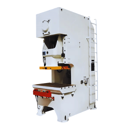
Safety light curtains installed at the operator access of an industrial press machine
Safety light curtains installed at the front operator access of a press machine. Final safeguard position and suitability require machine-level engineering evaluation.
01

Die & Tooling Area

The point of operation can create crushing, shearing, trapping and other serious hazards. Where a safety light curtain is used, the protective field must be positioned so the required safe condition is achieved before the approaching person can reach this area.

02

Front Operator Access

Manual loading, unloading and part positioning can repeatedly bring the operator toward the point of operation. This can be a suitable location for electro-sensitive protection when the machine and complete safety function permit it.

03

Side & Rear Access

A front light curtain does not prevent a person from reaching the hazard through an unprotected side or rear route. These access paths may require fixed guarding, interlocked guarding or other suitable safeguards.

04

Feed & Transfer Area

Feeders, conveyors, robots and transfer equipment can introduce additional crushing, trapping and movement hazards. These hazards should be assessed as part of the complete press system.

05

Reach-Over & Reach-Under Paths

Safeguard height and position should account for foreseeable reaching over, under, through or around the protective field according to the applicable safety requirements and installation geometry.

One press can require more than one safeguarding method.

The ENT safety light curtain protects only the access path covered by its sensing field. It should not be treated as a substitute for guarding or other protective measures at hazards that remain physically accessible outside that field.

04 · Safety Architecture

From Light Curtain Detection to Hazardous Motion Stop

The ENT safety light curtain detects an intrusion into its protective field, but the machine safety function continues beyond the sensor. The complete stop chain must be considered from detection through safety logic and the press control system to the final safe machine response.

System Principle

The safety light curtain is one component of the safety function. It should not be described or engineered as a standalone device that independently stops hazardous press motion.

Typical Safety Signal Path

Detection → Safety Logic → Machine Control → Safe Response

01
ENT Safety Light Curtain
Detects interruption of the protective field and changes its safety-related output state.
02
Safety Relay or Safety Controller
Processes the protective-device signals according to the required safety-control design.
03
Press Safety Control
Interfaces the safety function with the machine control elements responsible for hazardous motion.
04
Hazardous Motion Stops
The machine reaches the safe condition required by the validated safety function.
Detection Layer
Safety light curtain
Safety Logic Layer
Safety relay or safety controller
Machine Response Layer
Press safety control and stopping elements
System Boundary

Do Not Treat the Light Curtain as a Standalone Machine Stop

The ENT provides the protective-device detection function and safety-related outputs. The machine designer must integrate those signals into the safety-related control system so that interruption of the protective field produces the required machine response.

The appropriate architecture depends on the machine risk assessment, required safety function, control system and applicable standards.

System Validation

Verify the Complete Stop Chain at the Machine

The safety function is not complete until interruption of the ENT protective field has been verified to produce the required safe response through the safety logic and downstream machine control.

Validation should consider wiring, output-device response, stopping performance and fault behaviour under the actual installed machine conditions.

Sensor response time is not the same as total machine stopping time.

The ENT response time is only one part of the complete safety-function timing. Depending on the applicable design method, the evaluation can also include downstream safety-control response and actual machine stopping performance. These values are important when determining the required safeguard position.

Need a safety logic interface for the application?
CCH safety relay modules can be considered where their functions and electrical characteristics match the required safety-control architecture.
View Safety Relay Modules →
05 · ENT Selection

Select Detection Capability From the Hazard — Not the Press Type

ENT Type 4 safety light curtains are available with 14 mm, 25 mm and 45 mm detection capability options. The correct choice depends on what must be detected, how personnel can approach the hazard, the available installation position and the resulting safety-distance requirements.

Selection Principle

Do not select resolution by saying “mechanical press = 14 mm” or “hydraulic press = 25 mm.” Two presses of the same type can require different protective-device configurations because their hazards, stopping performance and access geometry are different.

14 mm
Fine Detection Capability

For Applications Requiring Detection of Smaller Intrusions

The 14 mm platform provides the finest detection capability in the ENT range. It is typically considered where small hand or finger access toward the hazard must be detected and the protective field is positioned close to the operator approach.

The final installation position still depends on the complete safety-distance calculation and machine stopping performance.

Selection Focus
Fine detection · close operator access · point-of-operation safeguarding
25 mm
Medium Detection Capability

For Hand-Approach Safeguarding Where the Geometry Allows

The 25 mm platform provides a balance between detection capability, protection height and application flexibility.

It may be suitable where the safeguarding design is based primarily on detecting hand or arm approach through the protected opening, provided the calculated safety distance and access geometry remain acceptable.

Selection Focus
Hand approach · operator openings · general machine safeguarding
45 mm
Larger Detection Capability

For Applications Where Fine Finger Detection Is Not Required

The 45 mm platform may be considered where the protective concept does not require fine finger detection and the larger detection capability is compatible with the foreseeable approach to the hazard.

It should not automatically be substituted for a finer-resolution light curtain at a close point-of-operation simply because the protected opening is larger.

Selection Focus
Larger-object detection · access geometry · machine-specific safeguarding

Four Questions to Answer Before Choosing 14, 25 or 45 mm

Detection capability is only one parameter in the safeguarding design. Before specifying the ENT configuration, evaluate what can reach the hazard, where the sensing field can be installed and whether the machine can stop in time.

01
What Must Be Detected?
Finger, hand, arm or a larger intrusion through the access opening.
02
How Can the Hazard Be Reached?
Direct approach, reach-over, reach-under, side access or full-body entry.
03
How Fast Can the Press Stop?
Total response and stopping time directly affect the minimum installation distance.
04
Where Can the Curtain Be Installed?
Available space, protective height and bypass paths must all be considered.
Avoid

Selecting by machine name alone

“This is a hydraulic press, so use 25 mm” does not evaluate the actual hazard, stopping time or operator approach and can lead to an unsuitable safeguarding configuration.

Better Approach

Select from the required safety function

Define the hazardous area, foreseeable approach, required detection capability, total stopping time and minimum installation distance — then choose the ENT configuration that fits those requirements.

A finer detection capability does not remove the need for a safety-distance calculation.

Whether 14 mm, 25 mm or 45 mm is selected, the protective field must still be positioned so that hazardous motion is prevented or stopped before a person can reach the danger zone. Detection capability, approach geometry and total stopping time must therefore be evaluated together.

06 · Safety Distance

Position the Light Curtain From the Applicable Safety-Distance Requirements

A safety light curtain must be positioned so that personnel cannot reach the press hazard before the safety system has produced the required safe machine response. The calculation method depends on the applicable machine standard and regulatory framework — there is no single formula that should be applied to every press worldwide.

Core Principle

First determine which requirements apply to the machine. Then use the actual stopping performance, protective-device response and access geometry required by that framework to determine the safeguard position.

Safeguard Positioning
Protective Field → Required Separation Distance → Press Hazard
Detection

ENT Protective Field

The protective function responds when a person interrupts the active sensing field.

S
Required Distance
Determined from the applicable standard or regulation, machine stopping performance and safeguarding geometry.
Hazard

Point of Operation

The hazardous motion must reach the required safe condition before the approaching person can reach this area.

Two Requirements Paths Commonly Encountered in Press Projects

International machine designs commonly reference ISO safeguarding requirements, while U.S. mechanical power presses are also subject to specific OSHA provisions. These paths should not be mixed into one calculation.

Path 01 · ISO-Based Machine Design

ISO 13855:2024

Positioning and dimensioning safeguards relative to human approach toward machine hazards.

For applications using the ISO machinery-safety framework, ISO 13855:2024 is used to evaluate the position and dimensions of the protective detection zone relative to foreseeable human approach.

The evaluation must use the applicable approach geometry, overall safety-function response and machine stopping performance, together with the relevant reaching and supplemental-distance provisions.

Use the current ISO 13855 requirements for the actual safeguard orientation and approach.
Include the response of the protective device and downstream safety-related control system where required.
Use actual machine stopping-performance data rather than an assumed value for the machine type.
Evaluate foreseeable reaching over, under, through or around the protective field as applicable.
Path 02 · United States

OSHA 29 CFR 1910.217

Specific requirements for mechanical power presses in U.S. workplaces.

For an applicable U.S. mechanical power press using a presence-sensing point-of-operation device, OSHA specifies its own minimum safety-distance requirement.

Ds > 63 in/s × Ts
OSHA 29 CFR 1910.217(c)(3)(iii)(e)

In this OSHA formula, Ts is the press stopping time measured at approximately the 90° position of crankshaft rotation. This press-specific requirement should not be replaced by an ISO calculator.

Applies specifically to mechanical power presses covered by 29 CFR 1910.217.
Presence-sensing point-of-operation devices may not be used on presses using full-revolution clutches.
Areas of entry to the point of operation that are not protected by the sensing field require appropriate guarding.
Verify the complete applicable OSHA requirements before final machine installation.

Never Substitute Sensor Response Time for Machine Stopping Performance

ENT response time describes the response of the protective device. It does not describe how long the press takes to reach the required safe condition. Depending on the applicable calculation, protective-device response, safety-control response and actual machine stopping performance must be treated as the values defined by that standard or regulation.

01
ENT Response
Use the actual response time of the selected ENT configuration.
02
Safety Logic
Account for downstream safety-control response where required by the applicable calculation.
03
Press Stop Time
Use measured or otherwise validated stopping-performance data for the actual machine.
04
Access Geometry
Confirm foreseeable approach and bypass paths under the applicable safety framework.
Avoid

One formula for every press and every market

Applying an ISO calculator automatically to a U.S. mechanical power press — or applying the OSHA mechanical-press formula to unrelated machine types — ignores machine-specific and jurisdiction-specific requirements.

Correct Approach

Identify the applicable requirement first

Determine the machine type, destination market and applicable safety requirements, then calculate and validate the safeguard position using the correct method and actual machine stopping performance.

ISO-Based Applications
Safety Distance Calculator
Use the CCH calculator as a preliminary engineering tool for applicable ISO-based safety-light-curtain positioning. It does not replace U.S. OSHA mechanical-power-press requirements or final machine-level validation.
Open Safety Distance Calculator →
Do not estimate stopping time from the press type.

Two visually similar presses can have different stopping behaviour because of their clutch, brake, drive, hydraulic system, control architecture, condition or operating mode. Final safeguard positioning should use the stopping-performance data required by the applicable standard or regulation for the actual machine.

07 · Application Scenarios

Different Presses — Different Safeguarding Questions

Safety light curtains can be applied across different press applications, but the machine name alone does not determine the solution. Each project should be evaluated from its hazardous motion, operator interaction, access geometry, stopping capability and safety-control architecture.

Safety light curtain installed at an operator access area of a large industrial press machine
Industrial Press Application

Integrating Safety Light Curtains Around a Large Press Access Area

Larger press installations can have wide operator openings, multiple access routes and additional machine structures around the working area. A safety light curtain may protect a defined personnel approach where presence sensing is suitable for the machine and the required safety function.

The protective-device position must be evaluated together with the actual hazard location, machine stopping performance, required separation distance and any remaining routes around the sensing field.

Evaluate the complete installation — not only the visible light curtain.

A field photograph shows how protective equipment can be physically integrated around a machine, but final safety suitability depends on the complete risk assessment, control architecture, safeguard positioning and validation.

01
Press Application

Mechanical & Stamping Presses

Operators may repeatedly load blanks, position parts or remove finished components near the die area. Where presence sensing is appropriate for the machine configuration, a light curtain can protect the defined operator approach without creating a physical barrier across the normal working opening.

Particular attention should be given to stopping performance and the press clutch / control configuration before selecting the safeguarding method.

Confirm
Press operating and clutch / control configuration
Actual machine stopping performance
Operator approach to the die / tooling area
Side and rear access paths
02
Press Application

Hydraulic Presses

Hydraulic presses vary widely in size, movement, control design and operator interaction. A light curtain may be considered where personnel approach an open working area and interruption of the protective field can produce the required safe machine response.

Do not assume that slower visible movement automatically permits the sensing field to be installed closer to the hazard. The safeguard position must use the actual machine response and stopping performance required by the applicable safety framework.

Confirm
Hazardous closing and other relevant machine movements
Actual stopping-performance data
Front, side, reach-over and reach-under access
Required detection capability and protection height
03
Integrated Machinery

Automated Press Cells & Press Lines

Feeders, transfer equipment, robots, conveyors and other automation can turn a single press into a larger hazardous machine area. Safeguarding should therefore consider the complete cell and every foreseeable personnel access route, not only the front operator opening.

Safety light curtains may protect selected personnel access points, while other areas can require fixed guarding, interlocked access or other suitable protective measures.

Confirm
Press plus feeder / robot / transfer-system hazards
Personnel entry and service access points
Possibility of full-body entry into the safeguarded area
Safety-zone and restart strategy

The Engineering Sequence Is Similar Across Press Types

Whether the application uses a mechanical, stamping, hydraulic or automated press, product selection should follow the same basic sequence: identify the hazard, define the access path, establish stopping performance, determine the required safeguard position and then select the light curtain configuration.

01
Hazard
What hazardous motion can injure personnel?
02
Access
How can a hand, arm or person reach the hazard?
03
Stop Time
What is the actual machine stopping performance?
04
Distance
Where must the protective field be positioned?
05
ENT Selection
Which detection capability and protection height fit the design?
U.S. mechanical power presses require a machine-specific review.

For point-of-operation safeguarding on mechanical power presses, presence-sensing device suitability depends on the press configuration and applicable OSHA requirements. A Type 4 safety light curtain should not be represented as universally suitable for every mechanical power press.

Not sure which ENT configuration fits your press?
Send us the press type, machine photos, access opening dimensions, operator approach and available stopping-performance information. We can help narrow the suitable light-curtain configuration for further engineering evaluation.
Discuss Your Application →
08 · Reset & Restart

A Clear Protective Field Is Not a Command to Restart the Press

After a safety light curtain has been interrupted, several different events can occur: the protective field can become clear, the safety function can be reset, and the machine can later be permitted to operate again. These are separate conditions and should not be treated as the same event.

Restart Principle

Removing the obstruction from the ENT sensing field only restores the protective field to a clear condition. Hazardous press motion should resume only under the conditions defined by the machine’s validated safety-control design.

STATE 01

Protective Field Becomes Clear

A person or object leaves the active sensing field and the ENT is no longer detecting an interruption.

This indicates the status of the protective device only.

STATE 02

Safety Function Is Reset

Where reset is required, the safety-related control system permits the safety function to return to its ready condition only after the defined reset conditions have been satisfied.

Reset does not itself mean that hazardous motion must start.

STATE 03

Machine Operation Is Permitted to Resume

The machine’s validated start / restart logic determines when operation may resume after the protective condition has been restored.

Clearing or resetting the protective device must not, by itself, create unexpected hazardous movement.

Clear

Protective-Device Status

The ENT sensing field is unobstructed. This describes what the light curtain is detecting.

Reset

Safety-Function State

The safety-related control system returns the protective function to the state permitted by the machine safety design.

Start / Restart

Machine Operating State

Machine operation may resume only when the conditions defined by the validated machine safety and control design have been satisfied.

Where Manual Reset Is Required, It Should Be a Deliberate Action

The reset concept should be determined from the machine risk assessment and applicable safety requirements. Where a manual reset is used, the reset action should be arranged so that it is intentional and does not itself initiate hazardous machine movement. The machine designer should also consider whether the operator can verify that the safeguarded area is clear before performing the reset.

01
Reset Location
Consider whether the person performing the reset can verify the relevant safeguarded area.
02
Deliberate Action
Reset should occur under the conditions defined by the safety-control design rather than accidentally.
03
Restart Behaviour
Confirm that restoring or resetting the protective function cannot unexpectedly create hazardous movement.
Full-body access requires particular attention to restart behaviour.

If a person can pass completely through the protective field and remain inside the safeguarded area, simply restoring the light curtain field does not confirm that the area is unoccupied. The safeguarding and restart strategy must address this possibility as part of the complete machine safety design.

Before Commissioning

Four Questions the Integrator Should Be Able to Answer

01
What happens when the field is interrupted?
Verify the required safe machine response.
02
What happens when the field becomes clear?
Confirm that clear-field status alone cannot create unexpected hazardous movement.
03
When is reset permitted?
Define the reset conditions required by the machine safety design.
04
Under what conditions may machine operation resume?
Verify that the validated start / restart logic prevents unexpected hazardous movement after the protective condition is restored.
System-Level Function

Reset and restart behaviour are functions of the complete machine safety-control architecture. The ENT provides protective-field status; it should not be described as independently deciding when hazardous press motion may resume.

09 · Standards & Compliance

Put the Light Curtain Inside the Complete Press Safety Framework

Press safeguarding is not governed by one product rating or one standard. A complete design can involve risk assessment, press-specific safety requirements, protective-device requirements, safeguard positioning and safety-related control-system design.

Compliance Principle

A Type 4 safety light curtain may form part of a high-performance machine safety function, but its device classification does not by itself establish the PL, SIL or regulatory compliance of the complete press.

How the Standards Fit Together

From Machine Risk Assessment to the Final Safety Function

The applicable standards depend on the machine, market and intended safety function. The sequence below provides a practical view of the different roles these commonly referenced machinery-safety standards can play.

01
ISO 12100
Hazard identification, risk assessment and risk reduction.
02
ISO 16092 Series
Press-specific safety requirements where the relevant part applies.
03
IEC 61496
Electro-sensitive protective equipment such as safety light curtains.
04
ISO 13855
Position and dimensions of safeguards relative to human approach.
05
ISO 13849 / IEC 62061
Safety-related control-system design and functional safety.

This diagram is a practical overview of how commonly referenced standards relate to a press safeguarding project; it is not a formal standards hierarchy. The applicable machine-specific standards and regulatory requirements must be determined for the actual machine and destination market.

ISO 12100

Start With Machine Risk Assessment

ISO 12100 provides the general machinery-safety methodology for identifying hazards, estimating and evaluating risks, and applying risk-reduction measures throughout the machine life cycle.

This is why press safeguarding should begin with the actual machine hazard and foreseeable personnel interaction rather than with a light-curtain model number.

Role in a Press Project
Risk assessment foundation · hazard identification · risk reduction
IEC 61496-1 / IEC 61496-2

Safety Light Curtain / AOPD Requirements

The IEC 61496 series covers electro-sensitive protective equipment. Part 2 contains particular requirements for equipment using active opto-electronic protective devices such as safety light curtains.

This is where the protective-device Type classification belongs. It does not define the complete machine safety function or determine where the light curtain must be installed for every application.

Role in a Press Project
ENT / AOPD product requirements · Type classification
ISO 13855:2024

Safeguard Positioning Relative to Human Approach

ISO 13855 addresses the positioning and dimensioning of safeguards with respect to the approach of the human body or parts of the body toward machine hazards.

For applicable ISO-based light-curtain installations, it is directly relevant to the position of the detection zone, approach geometry and required separation distance.

Role in a Press Project
Separation distance · approach geometry · safeguard positioning
ISO 13849-1 / IEC 62061

Safety-Related Control-System Performance

ISO 13849-1 provides methodology for the design and integration of safety-related parts of control systems and uses Performance Level concepts.

IEC 62061 provides a machinery functional-safety route for the design, integration and validation of safety-related control systems using Safety Integrity Level concepts.

Role in a Press Project
Complete safety function · PL / SIL · control-system architecture
Press-Specific Standards

ISO 16092 Series — Machine Tools Safety · Presses

Where the machine is within their scope, the ISO 16092 standards add press-specific technical safety requirements on top of the general machinery-safety framework. The applicable part depends on the press design and drive technology.

ISO 16092-1
General Press Safety Requirements
General technical safety requirements for presses within the standard’s defined scope.
ISO 16092-2
Mechanical Presses
Additional requirements for covered mechanical presses, including part-revolution clutch and mechanical servo press categories.
ISO 16092-3
Hydraulic Presses
Additional technical safety requirements for hydraulic presses within the scope of the standard.
ISO 16092-4
Pneumatic Presses
Additional technical safety requirements for pneumatic presses within the scope of the standard.

Type, PL and SIL Describe Different Levels of the Safety Design

These terms are related to machine safety, but they should not be presented as interchangeable labels for the complete machine.

Type 4
Protective-Device Classification
Describes the relevant performance characteristics of the electro-sensitive protective equipment under IEC 61496.
PL
Performance Level
Used in ISO 13849 methodology when evaluating the safety-related control system that performs the required safety function.
SIL
Safety Integrity Level
Used in machinery functional-safety evaluation under standards such as IEC 62061.
United States · Mechanical Power Presses

OSHA 29 CFR 1910.217 Must Be Checked Separately

U.S. workplace requirements for mechanical power presses are not replaced by IEC or ISO product standards. Where 29 CFR 1910.217 applies, its press-specific requirements for safeguarding, presence-sensing devices and safety distance must be evaluated.

01
Machine Configuration Matters
A presence-sensing point-of-operation device is not permitted on a mechanical power press using a full-revolution clutch.
02
OSHA Has Its Own Safety-Distance Requirement
Applicable U.S. mechanical power press installations must follow the relevant OSHA safety-distance provisions rather than assuming an ISO calculation automatically replaces them.
03
Unprotected Access Still Requires Guarding
Entry to the point of operation that is not protected by the presence-sensing device must be addressed using appropriate safeguarding.
Component conformity is not the same as machine compliance.

The final press safety solution depends on the machine risk assessment, applicable press-specific requirements, safeguard position, safety-related control architecture, stopping performance, installation and validation. Product certificates and component ratings are therefore inputs to the safety design — not automatic evidence that the assembled press installation is compliant.

10 · Project Checklist

What We Need to Help Select a Safety Light Curtain

Press-machine light curtain selection becomes much more accurate when the application is evaluated from real machine information. You do not need to know the final ENT model before contacting us — send the application conditions first, and we can help narrow the suitable configuration.

Before Model Selection

The most useful information is not simply “I need a light curtain for a press.” Machine layout, access geometry and stopping-performance information allow the protective-device requirements to be evaluated much more meaningfully.

01

Press Type & Machine Configuration

Tell us what type of press or machine you are safeguarding and how the operator normally uses it.

Example: mechanical stamping press, hydraulic press, manual loading station, automated press cell.
02

Hazard & Operator Access

Explain where the hazardous motion is and how the operator can approach or reach it during normal production.

Front hand loading, open die area, side access, full-body entry or maintenance access.
03

Access Opening Dimensions

Provide the approximate width and height of the opening that needs protection. This helps determine the required protection height and physical installation arrangement.

Opening width × height, available mounting position and any space limitations around the machine.
04

Required Detection Capability

If the machine risk assessment already defines the required detection capability, tell us whether the application is based on 14 mm, 25 mm, 45 mm or another specified requirement.

If this is not yet known, send the access geometry and application information instead.
05

Machine Stopping-Time Information

If available, provide validated or measured information describing how long the machine takes to reach the required safe condition after a safety stop command.

Do not substitute the ENT sensor response time for the actual machine stopping time.
06

Safety Control Interface

Tell us how the protective device will connect to the machine safety system, if that architecture has already been defined.

Safety relay, safety PLC / controller, or existing machine safety-related control circuit.
07

Side, Rear & Bypass Access

Show whether personnel can reach the hazard around, above, below or behind the proposed protective field.

Include existing fixed guards, doors, openings and adjacent equipment where relevant.
08

Machine Photos or Layout Drawing

A few clear photographs often help us understand the application faster than a long written description.

Front view, side view, tooling area, operator position and proposed light-curtain mounting location.

Don’t Have All the Information Yet?

That is not a problem. For an initial discussion, start with the machine type, one or two clear photos, approximate opening size and a description of how the operator approaches the hazard. We can then identify which additional information is needed before a final configuration is selected.

Minimum Information for an Initial Application Review
If you are at the early stage of a project, these four items are enough to start the conversation.
01
Machine Type
What machine or press is being safeguarded?
02
Opening Size
Approximate width and required protected height.
03
Application Photo
Show the machine, operator position and hazard area.
04
Operator Access
Explain how personnel normally reach the work area.

From Application Information to ENT Configuration

Product selection should come near the end of the process, after the application conditions have been understood. Our initial review can help organize the protective-device requirements for further machine safety engineering.

STEP 01
Review Application
Machine, hazard, access and working arrangement.
STEP 02
Define Protection Need
Detection capability, protection height and mounting geometry.
STEP 03
Check Safety Distance
Evaluate response time, machine stopping performance and approach.
STEP 04
Select ENT Configuration
Match the protective device to the defined application requirements.
Product selection does not replace the machine risk assessment.

CCH can assist with safety-light-curtain application and product selection based on the information provided. Final machine risk assessment, safety-function design, installation, validation and regulatory compliance remain part of the complete machine safety engineering process.

Press Application Support
Send Us Your Press Application
Share your machine photos, access opening dimensions and application conditions. We can help you narrow the ENT safety light curtain configuration for your project.
Contact Us →
11 · Frequently Asked Questions

Press Machine Safety Light Curtain FAQ

Common questions about safety light curtain selection, installation, stopping distance and control integration for press-machine safeguarding.

01 Can a safety light curtain be used on a press machine?

Yes, a safety light curtain can be used on suitable press applications when interruption of the protective field can cause the safety-related control system to prevent or stop hazardous motion before the person reaches the danger zone.

Suitability depends on the machine configuration, hazard, access geometry, stopping performance, control architecture and applicable machine-safety requirements.

02 Can a safety light curtain be used on every mechanical power press?

No. The machine configuration must be evaluated before a presence-sensing device is selected.

For example, U.S. OSHA requirements place specific restrictions on mechanical power presses, including that a presence-sensing point-of-operation device is not permitted on a press using a full-revolution clutch. Applicable machine-specific requirements should always be checked.

03 How far should a safety light curtain be installed from the press hazard?

There is no single fixed distance that applies to every press. The required separation distance depends on the applicable machine-safety requirements, actual stopping performance, protective-device response and access geometry.

For ISO-based machine designs, safeguard positioning should be evaluated using the applicable ISO 13855 requirements for the actual approach and protective-device arrangement.

For U.S. mechanical power presses covered by OSHA 29 CFR 1910.217, the applicable OSHA press-specific safety-distance requirements must also be followed. The ISO safety-distance calculator should not be treated as a substitute for those OSHA requirements.

For applicable ISO-based applications, you can use the Safety Distance Calculator as a preliminary engineering tool before final machine-level validation.

04 Is the ENT response time the same as the press stopping time?

No. The ENT response time describes only the response of the safety light curtain.

The total safety-function response also includes downstream safety logic, machine control and the physical time required for hazardous motion to reach the required safe condition. The actual machine stopping performance must therefore be evaluated separately.

05 Should I choose a 14 mm, 25 mm or 45 mm safety light curtain for a press?

Do not choose the detection capability from the press type alone. The decision should be based on what body part or intrusion must be detected, how the hazard can be approached, the available installation position and the resulting safety distance.

A 14 mm system provides finer detection than 25 mm or 45 mm, but every configuration still requires application-specific evaluation.

06 Does a Type 4 light curtain make the complete press PL e or SIL 3?

No. Type 4 is a protective-device classification. The safety performance of the complete machine safety function must be evaluated from the sensor, safety logic, output devices, machine-control architecture, diagnostics, wiring and validation.

Product ratings are important inputs to the design, but they do not automatically establish the PL, SIL or regulatory compliance of the assembled machine.

07 Does the press automatically restart when the light curtain becomes clear?

Clearing the protective field only means that the obstruction is no longer detected. It should not be interpreted as an independent command to restart hazardous press motion.

Reset and restart behaviour must be defined by the complete machine safety-control design so that unexpected hazardous movement is prevented.

08 Can a front safety light curtain replace all guarding around the press?

No. A light curtain protects only the access path covered by its active sensing field.

Side access, rear access and routes over, under or around the protective field must be evaluated separately. Depending on the machine layout, the overall design may also require fixed guards, interlocked guards or other suitable protective measures.

09 Can the ENT safety light curtain connect through a safety relay?

Yes, where the electrical configuration and safety function are appropriate, the ENT safety outputs can be integrated through a suitable safety relay or safety controller before interfacing with the machine safety-related control circuit.

CCH also offers SRB safety relay modules for applications where their functions and electrical configuration match the machine design.

10 What information should I send CCH for press light curtain selection?

For an initial review, send the press or machine type, one or two clear machine photos, approximate access-opening dimensions and a description of how the operator approaches the hazardous area.

If available, also provide machine stopping-time information, required detection capability, protection height and the intended safety-control interface. We can then help narrow the suitable ENT configuration for further engineering evaluation.

Application-Specific Engineering Still unsure whether a light curtain fits your press?

Start with the machine layout and hazard rather than the model number. CCH can help review the light-curtain application and narrow the ENT configuration, while final machine risk assessment, safety design and validation remain part of the complete machine safety-engineering process.

12 · Press Application Support

Discuss Your Press Safeguarding Application

Start with the machine and hazard — not the light-curtain model. Send us your application information and we can help narrow the ENT safety light curtain configuration for your press safeguarding project.

01
Machine Photo
Front view and operator work area.
02
Opening Size
Approximate width and protected height.
03
Operator Access
Explain how personnel approach the hazard.
04
Stopping-Time Data
Include measured or validated data if available.
Engineering Boundary

CCH can support safety light curtain selection and application review based on the project information provided. Final machine risk assessment, safety-system design, installation, validation and regulatory compliance remain part of the complete machine safety engineering process.