Entre em contato com a QJKH Company

Updated Jun 2026 Reviewed by CCH Sensing Technical Team
Safety relay vs standard relay is, at its core, a question about failure, not a spec exercise. Standard relays just switch circuits. Safety relays add redundancy, self-monitoring, and force-guided contacts so a single hidden fault can’t leave a machine at risk. That one difference decides whether a welded contact quietly keeps a hazard live, or forces the machine into a safe state.
Quick Specs: Standard Relay vs Safety Relay
| Contacts | Standard: single set · Safety: force-guided (mechanically linked) per EN 50205 |
| Channels | Standard: single · Safety: dual-channel (redundant) with K1/K2 |
| Self-monitoring | Standard: none · Safety: cross-channel diagnostics + feedback (EDM) |
| Fault behavior | Standard: fault may stay hidden · Safety: single fault detected, output goes to safe state |
| Governing standards | Standard: general product norms · Safety: EN ISO 13849-1, IEC 62061, IEC 61508 |
| Where it fits | Standard: general switching/automation · Safety: E-stop, light curtains, safety gates |
Safety Relay vs Standard Relay at a Glance
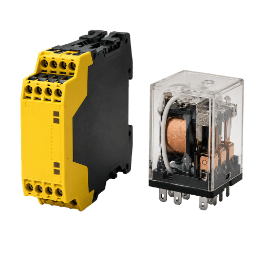
The short answer: A standard relay is a switch. Turn it on, it throws some contacts. Then, a low-power signal control some thing high-power, such as a light, fan, or starter. By contrast, a safety relay is a miniature, certified safety system. It does every thing a standard relay does, plus it includes redundant contacts, internal diagnostics that monitor its own state constantly, and special force-guided contacts to detect internal failures and prevent the machine from operating. The difference between a standard and a safety relay isn’t about “low quality”; it’s whether a single, unseen fault will compromise safety.
| Dimension | Standard relay | Safety relay |
|---|---|---|
| Primary job | Switch a control circuit | Execute and verify a safety function |
| Redundancy | None (single path) | Dual-channel, redundant |
| Self-monitoring | Não | Yes — used to monitor itself and the loop |
| Contacts | Independent | Force-guided (mechanically linked) |
| On a welded contact | May keep the load live, undetected | Detects the fault, blocks reset |
The table of CCH Sensing products mapped to EN ISO 13849-1 architecture categories.
What a Standard (Electromechanical) Relay Actually Does
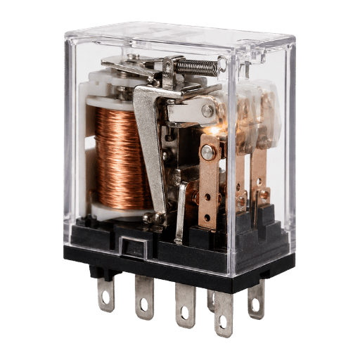
At heart, the standard relay is an electromechanical device. Energizing the coil creates a magnetic field that draws the armature, opening and closing the contacts; the output relay just follows the coil. It provides electrical isolation between a low-power input and the high-power load it switches, so it’s the workhorse of almost any automation machine.
It’s used to control light fixtures, conveyors, fans and pumps, and a normal relay can be used just about anywhere except where human safety is at risk. Where guarding is mandatory, that bar is set by OSHA’s 29 CFR 1910.212 machine-guarding rule. Standard relays are used in vast volumes, and the standard relay is available in an overwhelming array of footprints and voltage ratings; a single relay is capable of switching far more power than the signal driving it. For all-purpose switching, they’re the most economical option.
What limits them is structural: they’re built to perform one function at a time, and have no internal checks. A standard relay performs its task reliably, right up until the day a contact fail and sticks closed. At that point, it offers no indication to the operator or maintenance staff-and there’s a silent hazard just waiting. That’s fine for many applications, but dangerous when the hazard is moving parts within reach of people.
⚠️ Common misconception
Wiring two conventional relays in series isn’t “safe enough.” These two contacts might look “double protected,” but when one sticks closed, the second contact just repeats the same (lost) protection as the first. This is a common, well-understood point among professionals designing machines with safety in mind – even when using redundancies like series contacts doesn’t increase your safety’s Performance Level, there’s still a hidden, deadly risk lurking.
What a Safety Relay Is, Redundancy, Self-Monitoring, Force-Guided Contacts
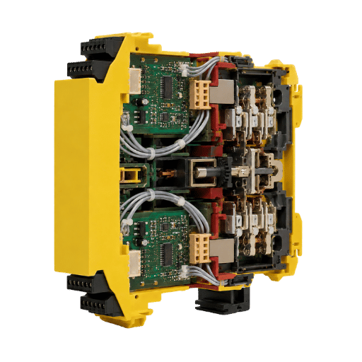
Standard relays and safety relays are two distinct device classes. Three structural features define a safety relay that a standard relay doesn’t have. First, redundancy: two independent relays, usually labelled K1 and K2, carry the safety function, so no single device is alone in the switching line.
Second, self-monitoring: integrated test circuitry compares the two channels every cycle, and the device is used to monitor whether its own outputs actually drop out when commanded. Third, force-guided contacts, the feature that makes the first two trustworthy.
That safety relay working principle is simple: redundant relays that execute a safety function and, via the safety contacts, drop the load to a safe state the moment a fault appears. Safety relays are used to monitor a safety device, and these built-in safety features and redundancy are exactly what a standard relay cannot be used to replicate. The function of a safety relay is reliable fault detection, not fault-free operation; on a real loss of the safety function, the devices with built-in safety features force a safe state instead of staying silent.
What is a force-guided contact in a safety relay?
In a force-guided (positively driven) contact, the normally-open and normally-closed contacts are mechanically linked so they can never both occupy the same state at once. If a normally-open contact welds closed, the linked normally-closed monitoring contact is physically prevented from closing; the monitoring circuit sees the state change that never happened, flags a fault, and refuses to allow a reset, so the welded contact can’t hide.
Control Engineering describes the same principle: in a force-guided design, if a make contact is welded closed, the break contacts cannot re-close. The positively-driven construction also appears in patent filings such as HK1242047A1.
📐 Engineering Note
EN 50205 (relays with forcibly guided contacts) in conjunction with the relevant sections of EN/IEC 60947-5-1 (control-circuit devices) cover forcibly guided behavior. In effect, mechanical link ensures that a hidden contact weld becomes a clearly identifiable disparity between the NO and the NC contact. CCH SR-Series modules employ this configuration and meet both EN ISO 13849-1 Category 4 / PL e and IEC 62061 SIL 3.
Reference Specs: a force-guided safety relay (CCH SR-Series)
| Safety rating | Category 4 / PL e (EN ISO 13849-1); SIL 3 (IEC 62061 / IEC 61508) |
| Output contacts | 6 A / 250 V AC (resistive), force-guided per EN 50205 |
| Supply / input | 24 V DC, dual-channel |
| Tempo resposta | 10–40 ms typical; release < 100 ms |
| Housing width | 22.5 mm / 45 mm on 35 mm DIN rail |
| Ambient temp | −25 °C to +55 °C; terminals 0.2–2.5 mm² |
| Approvals | TUV, CE, RoHS; ISO 9001 manufacture |
Source: CCH Sensing SR-Series data.
“Customers ask us to prove a safety relay is more reliable than a good standard relay. It usually isn’t, both can weld a contact. The safety relay’s job is not to never fail; it’s to make sure that when it does fail, the failure is visible and the machine stops. That’s what the force-guided contacts and the second channel buy you.”
Application Engineer, CCH Sensing
The Core Difference, Point by Point: A 12-Point Teardown
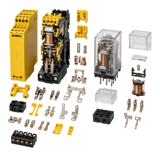
In a 12-Point Standard-vs-Safety Relay Teardown not available in the vendor brochures, I explore side by side what separates a safety relay from a standard relay. They multiply their differences in entire 12-point stack of contacts, use the details on this analysis rather than slogans, for the individual choices you’ll make about every individual component feature.
| # | Dimension | Standard relay | Safety relay |
|---|---|---|---|
| 1 | Purpose | General switching | Defined safety function |
| 2 | Contacts | Independent | Force-guided (EN 50205) |
| 3 | Channels | Single | Dual / redundant |
| 4 | Self-monitoring | None | Cross-channel diagnostics |
| 5 | Feedback / EDM | Não | Monitors external contactors |
| 6 | Fault on weld | Hidden | Detected, reset blocked |
| 7 | Fail-safe state | Undefined | Predefined safe state |
| 8 | Padrões | General | EN ISO 13849-1, IEC 62061/61508 |
| 9 | Third-party certification | Usually none | TUV / certified to a PL or SIL |
| 10 | Footprint | Smaller | Larger (22.5–45 mm typical) |
| 11 | Unit cost | Low | Higher (see cost section) |
| 12 | Where it belongs | Non-safety switching | Hazardous-motion safety |
Source: CCH Sensing teardown, cross referenced EN ISO 13849-1 and EN 50205.
✔ Safety relay advantages
- Single-fault tolerance with detection
- Certified route to PL d/e or SIL 2/3
- Monitors downstream contactors (EDM)
- Predictable, predefined safe state
⚠ Limitations / trade-offs
- Higher unit price and panel space
- Overkill for genuinely low-risk switching
- Pulse-test compatibility must be checked
- Still needs correct wiring to deliver its PL
Why a Standard Relay ‘Works’ Until It Doesn’t, The Single-Fault Test
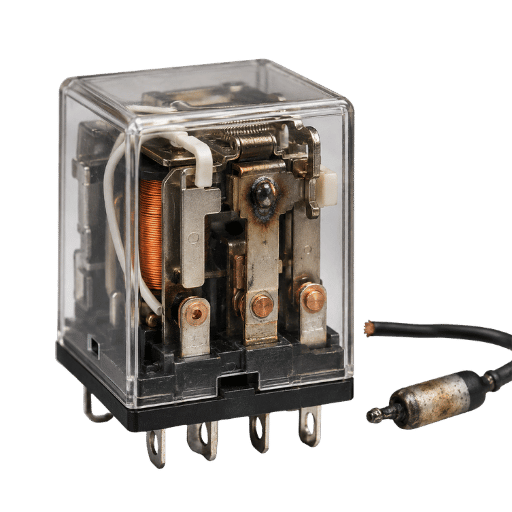
An ordinary relay can keep a guard circuit safe for years and look completely benign. Where there’s risk isn’t that it’s unreliable in general; where there’s risk is when it fails, nothing tells you about the failure. How do you easily decide whether that risk matter? The rule of thumb is the one question rule: The Single-Fault Test.
The Single-Fault Test
“Can one undetected failure leave the hazard energized?” If the honest answer is ‘yes,’ that regular relay isn’t adequate, and a safety relay or equivalent redundant/monitored implementation must be used.
“The textbook failure mode is contact welding under an inductive load. Let’s say there’s 7.5kW motor starter or mixing line drive controlled by a regular relay. Each time the drive turn off, inductive kickback across the contact arc that could eventually weld it together. When commanded ‘off’, the coil picks out, but the contacts welded together stay closed. The relay has two outputs (or a normally closed contact which the output is sensed) but these can’t detect the welding to give indication.” (An engineer describing a failure on Reddit r/PLC. This describes a situation where once a weld occurs, a second device is required to take power off). For machines such as power presses, OSHA’s control-reliability requirement (29 CFR 1910.217) is explicit that a single component failure must not prevent the stop.
“Safety relays prevent that weld from becoming dangerous.” By mechanical linking force-guided safety contacts, both contacts open every time. Because the devices actually read each contact and compare against their partner for conformity in each cycle, a weld will cause an error condition and the unit will prevent resets until the weld is addressed. As evidenced by CCH Field returns, the welded contact failure is the most frequent reason for a customer to migrate from a standard relay controlled guarding function to one of our SR-Series Safety Relay modules.”
When Do You Actually Need a Safety Relay?
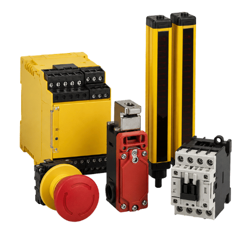
You need a safety relay whenever a risk assessment to EN ISO 13849-1 or IEC 62061 calls for Performance Level d or e, or SIL 2 or 3, on machinery that can cause injury. Below that threshold, a standard relay is fine. What really decides it is whether one undetected fault could leave hazardous motion running.
When should you use a safety relay?
You’ll need a safety relay when a risk assessment to EN ISO 13849-1 requires Performance Level d or e, or IEC 62061 SIL 2 or 3.
If the risk assessment rates your situation a PLr a, and nothing would be expected to happen during a single point of failure, you likely don’t need a safety relay. An enclosed guard gate that exposes no one to hazardous motion when it opens, even if the holding circuit fails on.
Here lies the difference between hype and reality, “you will always need a safety relay is untrue”. That being said, once a system presents any stoppable hazardous motion to people, the ISO 13849 risk-based selection usually leads the path toward a safety relay, as it’s the simplest way for engineers to address this issue.
5-Signal Safety-Relay Trigger Checklist
- The machine function is that of an emergency stop, or some interlock.
- Risk is greater than or equal to PLr d, or is assigned an IEC 62061 SIL rating.
- Monitoring downstream output contacts(welded contact monitor/EDM) is required.
- ✔ An auditor or customer requires documented PL/SIL conformity.
Pick three or more items on the checklist, and you’ve found your candidate safety relay.
💡 Worked example: risk graph to relay class
A robotic welding cell: severity S2 (serious injury), frequency F2 (frequent exposure), possibility of avoidance P2 (hard to avoid). Run those through the EN ISO 13849-1 risk graph and you land at PLr e. PL e needs Category 4 architecture – dual-channel, single-fault tolerant, with fault detection – which a single standard relay cannot provide. A force-guided safety relay (or safety controller) is the straightforward answer, wired for two channels with feedback. You can map the same inputs in our safety relay module selection guide.
Wiring Reality, Single vs Dual Channel, K1/K2, Feedback
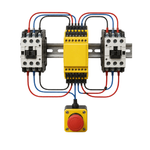
Hardware only delivers its rated Performance Level if it’s wired correctly. This is where a safety relay and a standard relay diverge most visibly on the panel.
What do K1 and K2 mean on a safety relay?
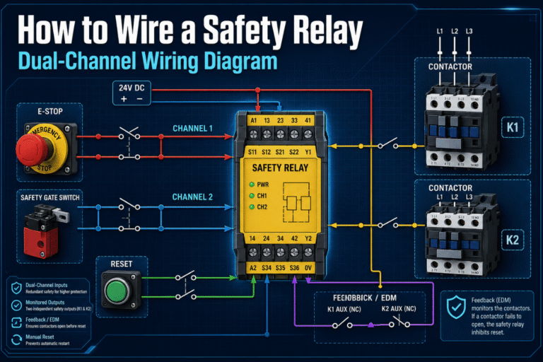
K1 and K2 are the two internal (or directly controlled) relays that form the safety relay’s redundant output channels. Each one is capable of opening the safety circuit on its own. Internally the device constantly compares them: if K1 and K2 disagree – one drops out, the other stays welded – the relay considers it a fault, opens the outputs, and prevents reset.
In practice the safety relay detects a fault the instant a contact welds, and teams choose a safety relay since that visibility is the whole point. That cross-check between K1 and K2 is what gives the safety relay its single-fault tolerance.
A single-channel circuit has one wire path through the e-stop to the relay; one break in detection and your safety function is lost. A dual-channel circuit run two independent paths, so a short or an open in one path can be cross-checked against the other. For PL e, dual-channel input with cross-monitoring is really a necessity – it’s the only way to achieve single-fault tolerance without compromising the safety function. That dual-channel architecture is what EN ISO 13849-1 Category 4 calls for.
📐 Engineering Note
External Device Monitoring (EDM), also known as feedback monitoring, wires the auxiliary (normally-closed) contacts of your downstream contactors back to the safety relay. If a contactor welds, its NC feedback contact will never reclose, and the safety relay will detect the inconsistency and deny re-enablement. This extends the fault detection capabilities of the safety relay to the power contactors specifically controlling the motor. There’s no comparable feature in a standard relay – a point you should check before installing safety relay modules across machines.
In one CCH distributor project, 24 press brakes in a production shop were retrofitted from a standard-relay two-hand control to SR-TH two-hand safety modules. Because the wiring followed printed dual-channel diagrams with EDM rather than a PC configuration file, each 22.5 mm module was installed in under four weeks per machine, with a typical 10–40 ms response time, fast, low-cost swaps across that many machines with no software toolchain. Here’s why this matters in practice: a single standard relay on the same two-hand circuit has no feedback path, so a welded downstream contactor would have stayed hidden.
Relay vs Safety Relay vs Contactor vs Safety PLC, Where Each Fits
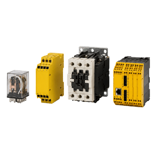
“Safety relay vs standard relay” is just one example of a broader family. Understanding where each component applies prevent misapplication of a safety PLC for a single e-stop, or the overuse of a standard relay for a guarded robot. This map places the common options for each device group.
| Device class | Switching tech | Self-monitoring | Typical role / when to choose |
|---|---|---|---|
| Standard EMR | Electromechanical | Não | General switching, non-safety |
| Solid-state relay (SSR) | Semiconductor | Não | High-cycle/quiet switching, non-safety |
| Reed relay | Reed switch | Não | Low-current signal switching, non-safety |
| Time-delay relay | EMR + timer | Não | Sequencing / off-delay, non-safety |
| Safety relay | Force-guided EMR | Sim | 1–3 safety functions (e-stop, gate, light curtain) |
| Safety timer relay | Force-guided EMR + delay | Sim | Delayed safe-stop (e.g., run-down guarding) |
| Safety contactor | Power EMR + mirror contacts | Partial (mirror) | Switching motor power within a safety circuit |
| Configurable safety relay | Force-guided EMR + logic | Sim | 4–8 functions without full PLC |
| Safety PLC | Programmable, redundant CPU | Extensive | Many functions, diagnostics, flexible logic |
Source: CCH Sensing device classification.
In practice, the boundary between a safety relay and safety PLC is a matter of quantity and change, with both routes validated under CEI 62061 and EN ISO 13849-1. Where a safety relay is simpler and less expensive, up to a few channels or functions is no problem, you’re in the land of safety PLC when you’ve multiple safety functions, frequently changing logic or rich diagnostics that require too much wiring and maintenance to implement in anything less versatile. Electromechanical, Solid-state and Reed all describe the relay’s contact method; Safety relays are an architecture- redundancy, monitoring and forced contacts, not another category of relay. Safety light curtains and other area-guarding safety devices are typically wired into safety relays of the following ilk.
One final distinction worth naming: in machine safety, an industrial safety relay de-energizes hazardous motion, a process safety relay can also see use in a safety instrumented system (SIS), reporting on normally energized fault conditions or trips a system when a de-energized fault is seen and reported. Industrial safety circuitry on the factory floor routes an emergency stop or a safety door switch into compact safety modules. Beyond the visual difference between a standard relay and a safety relay (the yellow housing), the first-generation safety relay is based on individual relays hardwired into a redundant configuration by the machine builder by hand. Modern force-guided relays put this logic onto one certified safety device.
Cost & Lifespan, Why Safety Relays Cost More
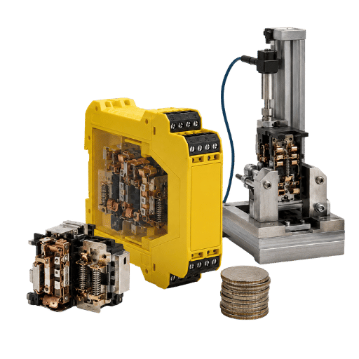
A safety relay costs materially more than a standard relay, and the reason starts with conformity. A safety relay must comply with safety standards such as EN ISO 13849-1 and CEI 62061 and meet safety integrity targets a general-purpose part never has to; a safety relay is designed and certified so that safety relays ensure the output reaches a safe state, and a safety relay provides documented PL/SIL conformity a standard relay does not. Safety relay manufacturers also carry the certification and testing burden, which is why a safety relay requires a long design cycle and is more costly compared to a standard relay. The extra hardware, redundant relays, monitoring electronics, and third-party certification, adds to the bill of materials, and installation and wiring costs sit on top. As a concrete anchor, a widely used dual-channel e-stop reference unit, the Pilz PNOZ X2.8P, has listed roughly in the $370–475 range on the open market depending on quantity and seller (observed June 2026; prices vary). A general-purpose standard relay for the same panel is typically a few dollars. That gap is real and worth respecting.
But unit price is only one piece of the total five-year ownership cost. The installation, wiring, the cost of a failed ( undetected) circuit will eventually show up. A monitored safety relay that catches a welding contactor will do what a cheap, run-of-the-mill, cheaper, ordinary one can’t. Be honest – a standard, typical relay’s installed and functioning five-year cost is likely only half that of a monitored safety relay, not the reverse.
📐 Engineering Note
If you’re going to compare service life you must compare apples to apples; it’s not that the monitored contacts and force-guided force of the safety relay wear out faster, it’s that they expose wear in a way they’re designed to in order to meet performance standards. Take a CCH distributor’s customer who consolidated a mix of 12 standard and safety components on a 50-line flowpack OEM down to five SR-Series safety relays; over the last 18 months there have been no SR-Series safety-relay warranty claims on that machine. That win was built on standardization, not longevity.
What’s Changing, ISO 13849-1:2023 and Relay Selection
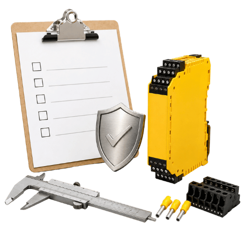
Right now, the biggest pressure shaping decisions between standard and safety relays isn’t market trends; it’s regulation. For 2023 a new standard came out – EN ISO 13849-1:2023 – this is the fourth edition of the standard which replaces the 2015 version with updates that tighten the specifications required for safety related parts of control systems.
For the engineer or the buyer comparing standard versus safety relay designs, this reinforces the simple conclusion that in order to fulfill the verification required for PL d or PL e- functions, the architecting solution typically relies on the force-guided safety relay.
Although we should be upfront; not everyone on the planet agrees with the 2023 revision. We saw functional-safety consultant Doug Nix publicly advocate against adopting this newest standard in its current form, and in practice, there’s an ongoing process during this transition period where many engineers continue designing and verifying the machine to the 2015 edition of the standard. What matters for the designer or buyer, whether for today or for the next machine, is to double check exactly which edition the customer/auditor demands before you finalize any drawings. Assuming that “latest means” approved is a gamble at this time, as in spite of which standard edition is specified, the tried and true methodology for any force guided (redundant, monitored) architecture to fulfill PL d or PL e is always a monitored and redundant solution, not the capability to just substitute standard devices; standards evolve how you verify; they generally don’t magically imbue cheap devices with new capabilities. One concrete risk for a plant is real: if you keep a legacy standard-relay guard circuit on a machine you later modify, an auditor can fail the whole line because the control reliability was never re-validated to the current edition. That gap is structural, the standard now expects documented diagnostic coverage that a single unmonitored relay simply cannot show. Because of that, CCH SR-Series modules ship certified to EN ISO 13849-1 Category 4 / PL e and SIL 3 (IEC 62061) at 6 A / 250 V AC, so the force-guided safety relay stays the low-risk route no matter which edition your auditor enforces. (For context only: the global safety-relay-and-timers market has been charted at the sub-$3bn level, with growth projected in the mid single digits, directional market background rather than a load-bearing claim.)
Perguntas frequentes
Q: What is the difference between a safety relay and a standard relay?
View Answer
A standard relay simply switches a circuit on or off. A monitored safety relay does more, by adding redundancy of signaling, internal self-monitoring, and a physical linkage of normally-open contacts (forced guided contacts). If a contact welds shut, the safety relay’s output will be forced to a safe state instead of leaving a hazard energized. A safety relay is certified to a Performance Level or SIL; a standard relay is not.
Q: What are the three types of relays?
View Answer
The three core relay technologies are the electromechanical relay (EMR), the solid-state relay (SSR), and the reed relay, each switching a circuit by a different physical method. A safety relay is not a fourth type on that list. It is an architectural approach, force-guided contacts plus redundant self-monitoring, built on top of those technologies to carry a defined safety function. Wiring two EMRs in series does not create that monitoring, so it is not equivalent.
Q: What is the purpose of a safety relay?
View Answer
A safety relay monitors a safety device, an emergency stop, light curtain, or safety gate, and drives the machine to a safe state when that device is actuated or an internal fault is detected. Its job is dependable fault detection, not fault-free operation.
Q: Can standard relays be used for safety applications?
View Answer
Only for genuinely low-risk functions, or none at all. Once a risk evaluation under EN ISO 13849-1 needs single-fault tolerance (PL d or e), a standard relay falls short: it has no redundancy and no self-monitoring, and wiring two in series adds no fault detection.
Q: Are safety relays mandatory for all industrial machines?
View Answer
No. They’re used where a risk assessment requires them, not on every machine. Many machines need them for emergency stops, guard doors, and light curtains rated PL d or e; genuinely low-risk equipment with no reachable hazardous motion usually does not need one.
Q: What is pulse testing (OSSD) in safety relays?
View Answer
Pulse testing a safety output (OSSD) involves switching the safety output off for nanoseconds to verify that the circuit and relay contacts can open. This checks for faults and shorts that a steady-state signal will not detect. When placing an safety relay on the power and control circuit that is pulse tested, assure that it can handle the pulsing, or contacts may chattering and lessen its lifespan. Check OSSD pulse compatibility before installing.
Q: How long does a safety relay last vs a standard relay?
View Answer
Both depend on switching load, contact rating, and cycle count, so raw electrical life is broadly similar for an equivalent contact rating. The safety relay’s advantage is that it will signify deterioration before it becomes dangerous instead of lessening in raw cycles.
Related Articles
Proper light curtain size and not sure a standard relay will pass inspection? CCH SR-Series force-guided safety relays deliver Category 4 / PL e and SIL 3 reliability, with pictures of wiring for a 24-press brake two-hand safety retrofit and a 50-line flowpack consolidation, and no PC programming needed.
About This Analysis
This comparison of safety relays and standard relays draws on CCH Sensing’s SR-Series engineering data, force-guided contacts to EN 50205, Category 4 / PL e construction, and distributor field cases including a 24-press-brake two-hand retrofit and a 50-line flowpack consolidation, cross-referenced against EN ISO 13849-1, IEC 62061, and OSHA machine-guarding requirements. Reviewed by the CCH Sensing technical team.
References & Sources
- 29 CFR 1910.212, General Requirements for All MachinesOSHA
- 29 CFR 1910.217, Mechanical Power Presses (control reliability)OSHA
- ISO 13849-1, Safety of machinery: safety-related parts of control systemsISO
- IEC 62061, Functional safety of safety-related control systemsIEC
- Safety switching device with positively guided relay contacts (HK1242047A1)Google Patents
- Force-guided safety relayControl Engineering
- Commentary on ISO 13849-1:2023Machinery Safety 101 (D. Nix)