Entre em contato com a QJKH Company

Knowing how to wire a safety relay is mostly a matter of four terminal groups, power, inputs, reset, and outputs, landed so the device monitor your safety input and drops the machine to a safe state on any fault. In short, it comes down to four things: getting power to the right terminals, landing your safety device on the input channels, wiring the reset, and closing the feedback loop on the output side. A safety relay isn’t a normal relay with a label, it’s a self-checking device built around two redundant internal relays that drop the machine to a safe state when anything fails. Get the wiring right and you’ve a circuit that catches its own faults; get it wrong and you’ve a single point of failure hiding behind a green light.
Updated June 2026 · Reviewed by the CCH Sensing technical team
Quick Specs: Safety Relay Terminal Reference
| Logic power | A1 (+24 V DC), A2 (0 V) — powers the coil / internal logic |
| Channel inputs | S11/S12, S21/S22 — one or two safety input channels |
| Reset / feedback | S33/S34 — start, monitored reset and EDM feedback loop |
| Safety outputs (NO) | 13-14, 23-24, 33-34 — force-guided output contacts to contactors |
| Aux / signal (NC) | 41-42 — non-safety status signal, often to a PLC input |
What a Safety Relay Actually Does Before You Wire It
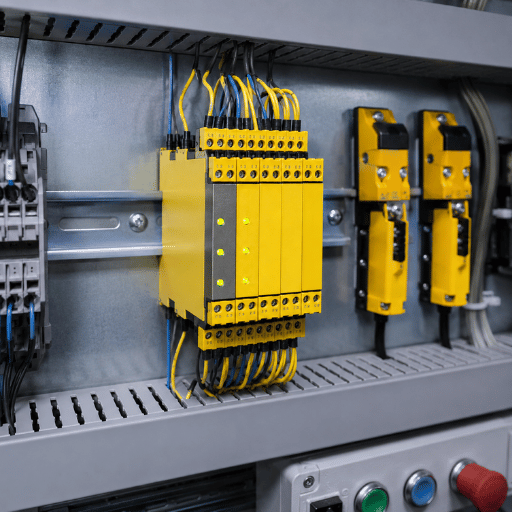
A safety relay watches a safety device, an emergency stop button, an interlock switch, a safety light curtainand forces connected machinery into a safe state when that device open or when the relay detects a fault inside itself. The “magic” lives in two internal relays, usually labeled K1 and K2, wired in redundancy with force-guided (positive-guided) contacts.
Redundant means the safety function runs through both K1 and K2, two redundant relays inside one housing; if one fails, the other still de-energizes the output. Force-guided means the normally open and normally closed contacts in each internal relay are mechanically tied, so a welded contact cannot lie about its state, the relay sees the disagreement and refuses to reset. This self-monitoring is exactly what regular relays cannot do, and it is the fault behavior that ISO 13849-1 targets, a single welded contact in an ordinary electromechanical relay can leave a machine running when it should be stopped. That difference is the whole basis of relay based safety circuits.
“The mistake we see most often on the bench isn’t a wrong wire, it’s treating the safety relay like an ice cube relay. People wire one channel, skip the feedback loop, and assume the green LED means they’re protected. The whole point of K1 and K2 is that the device proves itself safe on every cycle, not just the first one.”
Application Engineer, CCH Sensing
On our own bench, when we deliberately weld an output contactor on a CCH safety relay module and then call for a restart, the monitored feedback path holds the relay off, the circuit will not energize again until the fault is cleared. That behavior is the dividing line between a real safety device and a relay that merely looks like one. On a robotic weld cell we audited, that distinction is exactly why CCH Sensing engineers rate these modules to ISO 13849-1 PL e, because the relay must prove itself safe every cycle, not just at install. If you want the full comparison, see our breakdown of a safety relay vs a standard relay.
Do You Actually Need a Safety Relay?
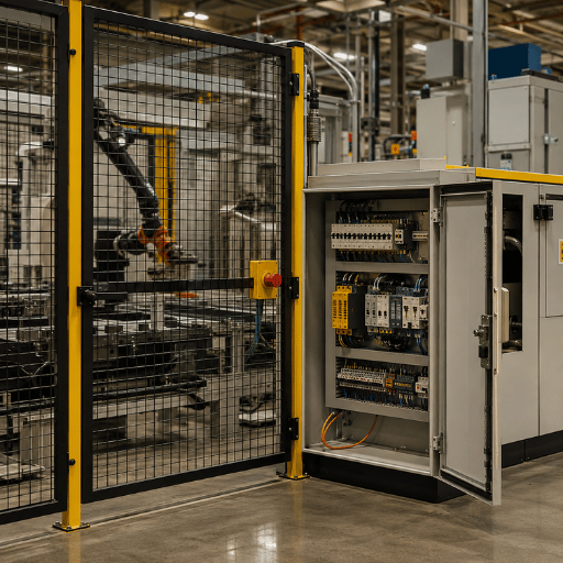
You need a safety relay whenever a risk assessment assigns a safety function a Performance Level that demands single-fault tolerance, Category 3 or 4 under ISO 13849-1:2023. At that point a plain relay or a single PLC input is no longer control-reliable, and only a dedicated safety relay or safety controller can deliver the redundancy the standard requires.
The Performance Level (PLr) itself is derived from severity, frequency of exposure, and possibility of avoidance; the equivalent metric under IEC 62061 is the Safety Integrity Level (SIL). That rating drives the Category you must build, so pin down these safety requirements before you choose hardware. In practice, CCH Sensing engineers map the risk assessment to a Category first, an in-house discipline built on years of OEM machine-safety projects.
When Can I Skip a Safety Relay?
You can skip a safety relay when the risk assessment lands at a low Performance Level and a stop failure couldn’t injure anyone, a conveyor that merely halts product with no operator reach-in is the classic example. Below Category 2, a standard relay or a single PLC input may satisfy the requirement, so the cost of a safety relay buy you nothing.
The moment a function needs Category 3 or 4 behavior, where a single fault must not cause loss of the safety function, that plain relay or PLC input is no longer control-reliable. General machine-guarding duty under OSHA 1910.212, and power-press control reliability under OSHA 1910.217, are the kinds of obligations that push a function toward a dedicated safety relay. Not sure where your function lands? Run the numbers with our PL/SIL category mapper or read the risk-based safety selection guide.
️ Important
Machine safety is a system property. A correctly wired safety relay only delivers its rated safety level if the input device, the wiring, and the output contactors all match that level. A relay cannot raise a Category 1 architecture to Category 3 on its own.
The 4-Terminal-Group Map: Decode Any Wiring Diagram
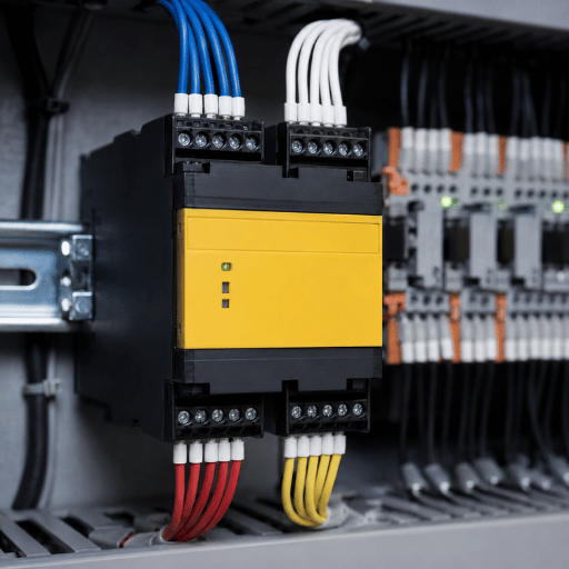
Every safety relay wiring diagram, regardless of brand, breaks into four functional groups. Learn the groups and you can read a Pilz PNOZ, an Allen-Bradley GuardMaster MSR, or a Siemens 3SK terminal block, and most published wiring examples, without memorizing part numbers. We call this the 4-Terminal-Group Map.
| Group | Typical terminals | What lands here |
|---|---|---|
| 1. Power | A1, A2 | 24 V DC supply to the coil and internal logic |
| 2. Inputs | S11/S12, S21/S22 | The safety device contacts — one channel or two |
| 3. Reset / feedback | S33, S34 | Reset button plus the external device monitoring loop |
| 4. Outputs | 13-14, 23-24, 33-34 (NO); 41-42 (NC) | Force-guided safety output contacts and a status signal |
A practical note on naming: output contacts are remarkably consistent across vendors, 13-14, 23-24 and 33-34 are normally open safety contacts and 41-42 is the normally closed auxiliary, a pattern confirmed across countless field diagrams. Input terminals vary more. On an Allen-Bradley dual-input relay, S11 and S21 send the test signal out and S12 and S22 receive it back, so the safety device sits between them. Always confirm the input convention on the datasheet before you land a single wire. In practice, the most common field mistake we see at CCH Sensing is a wire landed on the wrong input pair because a technician assumed one brand’s numbering applied to another, a five-minute error that only fails the validation test hours later. Group thinking prevents it, which is the reason ISO 13849-1 documentation starts from function, not part number.
How to Wire a Safety Relay, Step by Step
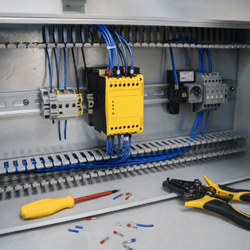
With the four terminal groups understood, the procedure is repeatable on almost any module. Wire a safety relay in seven steps: isolate power, energize A1/A2, land the safety device on the input channels, set the operating mode, wire the reset, connect the outputs to two contactors, then close the feedback loop and validate. This is the 7-Step Safety Relay Wiring Sequence we use as a bench checklist.
How Are Safety Relays Wired?
Safety relays are wired in pairs and in series: the safety device’s two channels land on the input terminals, the relay’s two redundant outputs drive two contactors, and the contactors’ mirror contacts return to the feedback terminals. Every safe path is doubled, so a single fault is always caught. The seven steps below put that structure into practice.
The 7-Step Safety Relay Wiring Sequence
- Isolate and lock out. Apply lockout/tagout per OSHA 1910.147 before touching the panel.
- Power the logic. Land 24 V DC on A1 and 0 V on A2. Confirm the power LED behaves as the manual describes.
- Land the safety device. Wire the emergency stop, interlock or light-curtain output onto the input channel(s) — S11/S12 for channel one, S21/S22 for channel two.
- Set the operating mode. Many relays have a selector (single vs dual channel, manual vs automatic reset). Power down, set it, power back up so the change is read.
- Wire the reset button across the reset/feedback terminals (typically S33–S34).
- Wire the safety outputs: take 13-14 and 23-24 to the coils of your two output contactors.
- Close the feedback loop and validate. Route the contactors’ mirror contacts back into the reset/feedback path, then test every channel.
Notice that the safety relay sits in the middle of the circuit: a safety input on one side, a monitored output on the other, and a reset that ties them together. That structure is identical whether you are wiring a guard interlock or a full machine guarding system. For the broader product context, our safety relay modules page and the safety relay modules guide cover module selection. On a typical production line retrofit, CCH Sensing engineers run this exact sequence because skipping step 7, the feedback loop, is the one failure that passes a first power-up yet fails an ISO 13849-1 validation later; budget roughly 20–30 min per safety function for wiring and test.
Single-Channel vs Dual-Channel Input Wiring
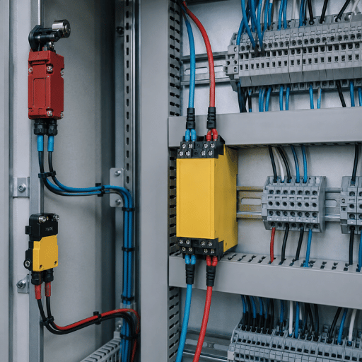
Your single biggest wiring decision is how many input channels to run. A single-channel input runs the safety device through one circuit; a dual-channel input runs it through two independent circuits wired in series, both of which must be closed for the relay to give an output. Dual-channel wiring is what lets the relay detect a cross-fault or a single broken wire, the foundation of Category 3 and 4 behavior under ISO 13849-1.
| Wiring | Fault detection | Typical category | Use when |
|---|---|---|---|
| Single channel | No single-fault tolerance | Up to Cat 1 | Low PLr, no reach-in hazard |
| Dual channel | Detects single fault + cross-fault | Cat 3 / 4 | Operator exposure, higher PLr |
In practice almost every guarded machine uses dual-channel input. Two normally closed contacts of an e-stop are wired so that pressing the button open both circuits at once; if only one opens, the relay flags a channel discrepancy and won’t reset. That’s the redundant input working exactly as intended. The mistake that bites integrators is running dual-channel wire but powering both channels from one source, which defeats cross-fault detection; CCH Sensing flags this in every customer audit because it quietly drops a Category 3 design back to Category 1, and the relay can only catch the discrepancy inside its simultaneity window of about 0.5 sec.
Wiring the Reset: Manual, Monitored and Automatic
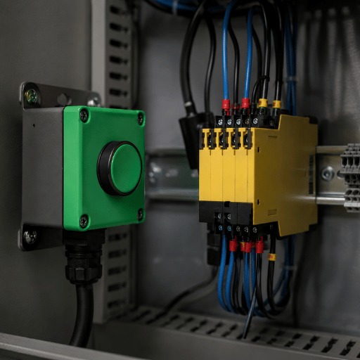
Reset wiring is where good circuits and dangerous shortcuts diverge. There are three options, and the choice is governed by the standard, not by convenience. Use the Channel-and-Reset Decision Grid to match the wiring to the application.
| Reset type | How it is wired | Use for |
|---|---|---|
| Automatic | Link the reset terminals; relay re-enables as soon as inputs are safe | Only where restart cannot create a hazard |
| Manual | Reset button across S33–S34; operator must press to re-enable | Guarded zones with operator access |
| Monitored manual | Reset button edge-detected on release, not on press | Highest assurance; defeats a jammed button |
Why does this matter so much? Because ISO 13850:2015 requires that resetting the emergency-stop function must not, by itself, restart the machine. A monitored manual reset satisfies this by detecting the falling edge when the button is released, a shorted or jammed reset button cannot fake a reset. In practice, CCH Sensing defaults guarded-zone designs to monitored reset, an in-house rule shaped by years of field retrofits. Field engineers learn this the hard way: setting every relay to automatic reset “to save a button” is a classic mistake that quietly removes restart protection.
Wiring the Output Side: Contactors, Feedback and the Welded-Contactor Trap
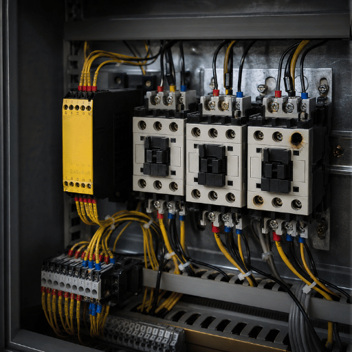
A safety relay’s output contacts are signal-rated, not motor-rated. They’re designed to switch the coils of two external contactors, which in turn switch the motor. Most relays give you two or three independent contact sets for exactly this reason. This is the Welded-Contactor Feedback Trap: the failure most beginners never plan for.
Should Safety Relay Contacts Switch 3-Phase Power Directly?
No. Never run motor current through the relay’s output contacts. Use the safety outputs (13-14 and 23-24) to drive the coils of two contactors, call them KM1 and KM2, and let those contactors switch the three-phase load. Two contactors, not one, so that a single welded set still leaves a second device to break the circuit.
Nota de Engenharia
Wire the normally closed mirror (auxiliary) contacts of KM1 and KM2 in series back into the feedback path (commonly S33–S34, sometimes Y1–Y2). This external device monitoring loop checks the contactors before each reset: if a contactor welds closed, its mirror contact stays open, the feedback loop never completes, and the relay refuses to re-energize. Size the output contacts conservatively, a typical safety output is rated a few amperes at 24 V DC, which is ample for contactor coils but nowhere near motor current.
What Happens If a Motor Contactor Welds Closed?
With the feedback loop wired, a welded contactor is caught on the next demand: the relay see the disagreement between commanded and actual contactor state and stays off. Without the loop, the welded contactor keep feeding the motor and the operator has no warning, because the green light is still on. That’s why external device monitoring isn’t optional on Category 3/4 circuits.
On a press brake we serviced, a single welded contactor had been feeding the ram for weeks behind a green light because nobody wired the feedback loop; CCH Sensing engineers now treat EDM as mandatory on every PL d or higher build under ISO 13849-1a rule earned in the field, on our in-house test bench and across years of OEM commissioning. Mirror the fault to a PLC output or indicator if you want maintenance to see it, but keep that signal out of the safety path.
Worked Example: Wiring an E-Stop Through a Safety Relay
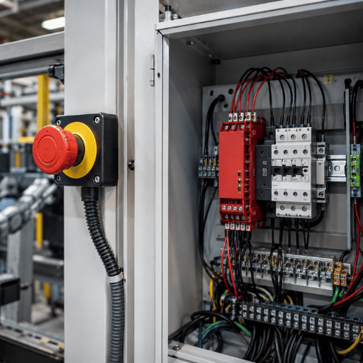
Here’s the whole circuit, terminal by terminal, for a dual-channel emergency stop driving a motor through two contactors, the most common safety relay wiring you’ll build. It’s the exact circuit CCH Sensing wires on the in-house bench for OEM customers, because a concrete worked example beats a generic diagram every time; years of panel builds have made it our default e-stop template.
- ✔ Poder:24 V DC to A1, 0 V to A2.
- ✔ Channel 1:first normally closed contact of the e-stop between S11 and S12.
- ✔ Channel 2:second normally closed contact of the e-stop between S21 and S22.
- ✔ Reset + feedback:reset button plus the series mirror contacts of KM1 and KM2 across S33–S34.
- ✔ Outputs:13-14 to the KM1 coil, 23-24 to the KM2 coil.
- ✔ Load:KM1 and KM2 main contacts in series feed the three-phase motor.
- ✔ Status:41-42 (NC) to a PLC input for indication only, never as the safety path.
Press the e-stop and both channels open, K1 and K2 drop, both contactors release, and the motor stops. Release and reset, and the relay re-enables only if the feedback loop confirms both contactors have actually opened. This circuit aligns with ISO 13850:2015 for the e-stop function and with the electrical practices in IEC 60204-1 for the machine wiring.
Testing, Commissioning and Troubleshooting
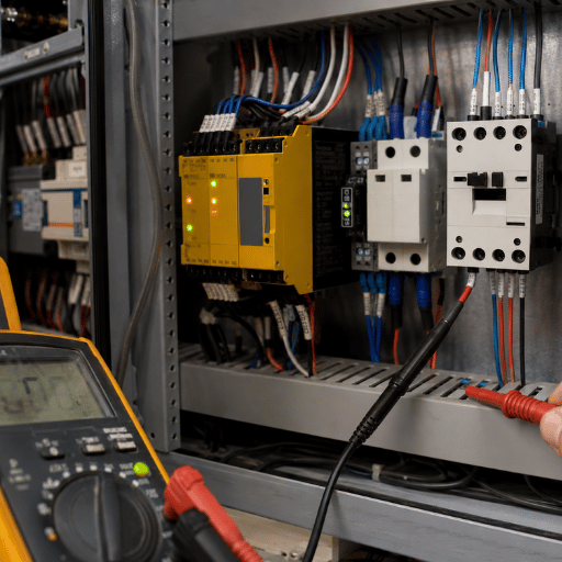
How Do You Test a Safety Relay?
Validation is part of the wiring job, not an afterthought. Work through each safety function in turn: trigger the device, confirm the outputs drop, then confirm the machine actually stop. A safety relay monitor its channels continuously, so the relay’s diagnostic LEDs are your first read on what it sees.
- ✔ Operate each safety input and verify both channels respond, a single-channel response means a fault or miswire.
- ✔ Confirm the output contacts open and the contactors release on every demand.
- ✔ Simulate a welded contactor by holding a mirror contact open; the relay should refuse to reset.
- ✔ Read the LED fault codes against the manual to localize cross-faults and channel discrepancies.
Common faults a safety relay detects and reports include a cross-fault between the two input channels, a welded output contact, a channel discrepancy (one input closed while the other is open), and a simultaneity timeout when the two channels do not change state within the allowed window. Each of these is a wiring story as much as a device story, most “the relay won’t reset” calls trace back to a feedback loop that was never closed. In the field, CCH Sensing engineers budget a full functional test per safety function because an untested channel is the root cause of most “it worked on Monday” failures; on the bench we deliberately fault each channel to confirm the relay reacts inside its rated response time and logs the fault per ISO 13849-1.
Industry Outlook: From Discrete Relays to Configurable Safety
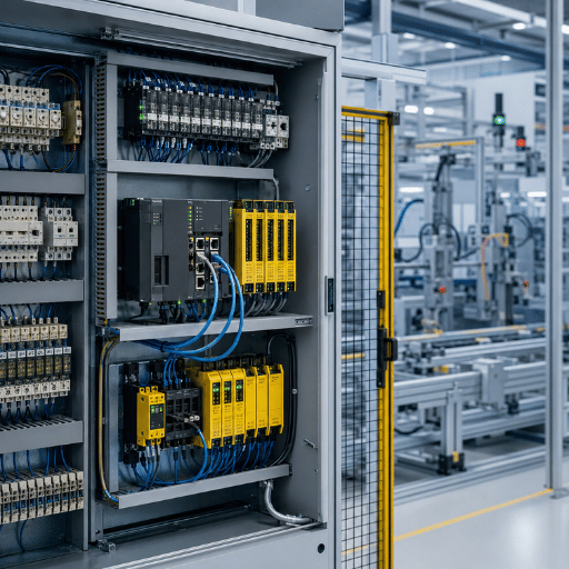
Those wiring fundamentals above are stable, terminal groups, dual-channel inputs and external device monitoring haven’t changed and won’t. What’s changing is the architecture you choose before you pick up a wire. As the number of safety functions on a line grows, point-to-point discrete relay wiring becomes the expensive part to install and, worse, to modify later. For any new build, the practical judgment is to decide between discrete relays and a configurable platform up front, because re-pulling wire after commissioning costs far more than choosing correctly on paper.
Two shifts drive that decision. Configurable safety relays, safety controllers and safety PLCs replace a stack of single-function relays with one software-defined device, trading wiring for configuration and turning a hard-wired safety system into a programmable one. And IO-Link Safety (standardized as IEC 61139-2 and now offered by Pilz, Phoenix Contact and SICK among others) carries safe and standard signals over a single cable to field devices, enabling distributed safety that cuts the point-to-point runs which dominate a traditional safety circuit. For a low-function machine, a discrete safety relay is still the cheapest, most transparent choice. For a line with a dozen interlocks and zones, increasingly the norm, the wiring savings tip toward configurable safety. On multi-zone lines we commission, the trade-off is concrete: a dozen discrete relays can mean hundreds of wired terminals, which is the reason CCH Sensing increasingly specs configurable safety for OEM builds with more than roughly 6 safety functions, because the wiring labor saved outpaces the higher unit cost, and ISO 13849-1 applies either way. Market analysts project steady growth in functional-safety hardware through the decade, but that figure is background; the decision that affects your panel is architecture-before-wire, not the size of the market.
Perguntas frequentes
Q: What is K1 and K2 on a safety relay?
Ver Resposta
K1 and K2 are the two internal, force-guided relays that give a safety relay its redundancy. Each safety function runs through both, and their contacts are mechanically tied so a welded contact is always detected. If either fails, the other still de-energizes the output, which is why a safety relay can fail to a safe state while a standard relay cannot.
Q: Can I use a safety relay output only to signal a PLC?
Ver Resposta
Use the non-safety auxiliary contact (41-42) for PLC indication, never the safety outputs as the only stopping path. A standard PLC input is not control-reliable, so the safety function must break power through safety-rated outputs and contactors. The PLC can read status and log events, but it cannot be the device that keeps the operator safe.
Q: What’s the difference between a safety relay and a master control relay (MCR)?
Ver Resposta
A master control relay removes power from a section of control circuitry, but it is a single, non-monitored device — a welded MCR contact is undetected. A safety relay adds redundant channels, force-guided contacts and self-monitoring so a single fault cannot defeat the safety function. An MCR is a convenience and a code requirement in some panels; it is not a substitute for a safety relay on a hazardous function.
Q: How many contactors do I need on the safety relay output?
Ver Resposta
For a Category 3 or 4 stop you need two contactors wired in series, each driven by one of the safety relay’s output contacts, with their mirror contacts fed back for monitoring. Two devices give single-fault tolerance: if one welds, the second still breaks the load and the feedback loop blocks the next reset. A single contactor is only acceptable on low-risk, lower-category functions where a welded contact would not create a hazard.
Q: Can you “link out” or bypass a safety relay?
Ver Resposta
No, never. Jumpering or “linking out” the inputs or outputs to make a machine run removes the safety function entirely, and it is both unsafe and non-compliant with ISO 13849-1. If a relay will not reset, diagnose and fix the wiring or the faulted device instead of bypassing it.
Q: What wire gauge and conduit do I use for safety relay control wiring?
Ver Resposta
Follow the machine’s electrical design and IEC 60204-1; control wiring is commonly sized around the device terminals and circuit protection rather than the tiny signal current. Keep safety wiring identifiable, protected against short circuits to adjacent conductors, and routed so a single fault cannot bridge both channels.
About This Wiring Guide
The terminal behavior and the welded-contactor feedback test described here come from bench work on our own CCH Sensing safety relay modules, cross-checked against ISO 13849-1, ISO 13850 and field practice. Wiring details vary by model, treat this as a reference and always confirm against your device’s datasheet. Reviewed by the CCH Sensing technical team.
Need a safety relay module rated for your Performance Level?
Referências e fontes
- ISO 13849-1:2023, Safety of machinery, Safety-related parts of control systemsOrganização Internacional de Normalização
- ISO 13850:2015, Safety of machinery, Emergency stop functionOrganização Internacional de Normalização
- OSHA 29 CFR 1910.212, General requirements for all machinesAdministração de Segurança e Saúde Ocupacional dos EUA
- OSHA 29 CFR 1910.147, The control of hazardous energy (lockout/tagout)Administração de Segurança e Saúde Ocupacional dos EUA
- OSHA 29 CFR 1910.217, Mechanical power pressesAdministração de Segurança e Saúde Ocupacional dos EUA
- US 6,882,155 B2, Remotely actuated, circuit testing emergency stopU.S. Patent and Trademark Office