Nehmen Sie Kontakt mit QJKH Company auf


An emergency stop safety relay is the monitoring device that sits between your E-stop button and the motor contactor, checking the stop circuit for faults before it ever lets the machine restart. Wire an E-stop straight to a contactor and you save a part, but you lose the one thing that make the circuit trustworthy: the ability to detect a welded contact, a shorted channel, or a broken wire. This guide shows how that monitoring works, how stop categories change the wiring, and how to design an E-stop circuit that holds its safety function even when a component fail.
In short: An emergency stop safety relay monitors a dual-channel E-stop loop, drives force-guided output contacts, and blocks reset until every fault clears. It does not replace machine guarding, under ISO 13850:2015 the emergency stop is a complementary protective measure. Its stop category (0, 1, or 2 under IEC 60204-1) and its target Performance Level decide whether one channel or two is enough.
Quick Specs
| Function | Monitors E-stop input; removes power through force-guided output contacts |
| Input | Single- or dual-channel N.C. (typical terminals S11–S12 / S21–S22) |
| Stop categories | 0, 1, 2 per IEC 60204-1 (E-stop uses 0 or 1 only) |
| Leistungsniveau | Up to PL e / Category 4 (ISO 13849-1); SIL 3 (IEC 62061) |
| Reset | Automatic or monitored manual (S33–S34) |
| Feedback | External Device Monitoring loop (Y1–Y2) |
| Control voltage | Typically 24 V DC (A1–A2) |
| Ausgangskontakte | Typically up to 6 A, 250 V AC (model-dependent) |
| Reaktionszeit | Typically under 0.1 s on trip |
| Mission time (TM) | 20 years assumed by ISO 13849-1 |
| Mounting | DIN rail, slim units from 22.5 mm wide |
| Maßstäbe | ISO 13850:2015 · IEC 60204-1 (EN 60204-1:2018/A1:2025) · NFPA 79 |
What an Emergency Stop Safety Relay Does, and Why You Can’t Wire the Button Straight to the Contactor
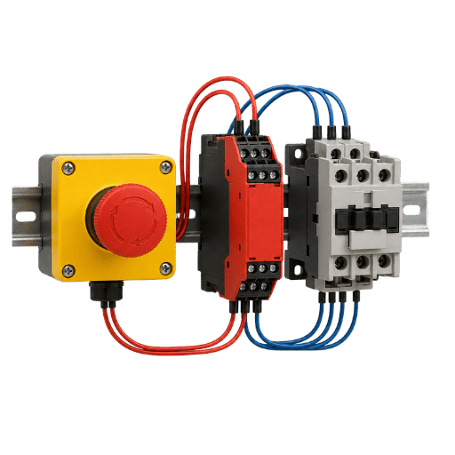
A bare emergency stop button is just two normally-closed contacts that open when pressed. That works until something breaks, and in a safety circuit, the question is never “does it work?” but “what happens when it fails?” If the motor contactor welds shut, a button wired directly to it can’t pull the load offline, and nothing warns the operator that the machine is now unstoppable. That hidden failure is exactly what a safety relay catches.
A safety relay watches the whole stop loop continuously. It looks for a broken wire, a short between channels, a contact that open too slowly, and, through its feedback loop, a downstream contactor that has welded closed. When it sees a fault, it de-energizes its outputs and refuses to reset until the fault clears. Practitioners on automation forums put the trade-off bluntly: adding the relay adds a component, but it converts a circuit that can fail silently into one that fail loud and safe. In practice, on any production machine with hazardous motion, that monitored relay is the certified link that turns a 24 V control signal into a verifiable safe stop, the difference between a circuit that look safe and one that’s provably safe.
Was ist der Zweck eines Sicherheitsrelais?
The purpose of a safety relay is to make a stop circuit single-fault tolerant and self-checking. It standardizes the redundancy, cross-monitoring, and reset logic that machine-safety standards require, so a single E-stop, light curtain, or interlock can reliably reach a defined Performance Level. Under ISO 13850:2015, the relay also enforces the rule that an emergency stop must latch and require a deliberate reset, it cannot clear itself when power returns.
How a Safety Relay Works: Dual-Channel Monitoring and Force-Guided Contacts
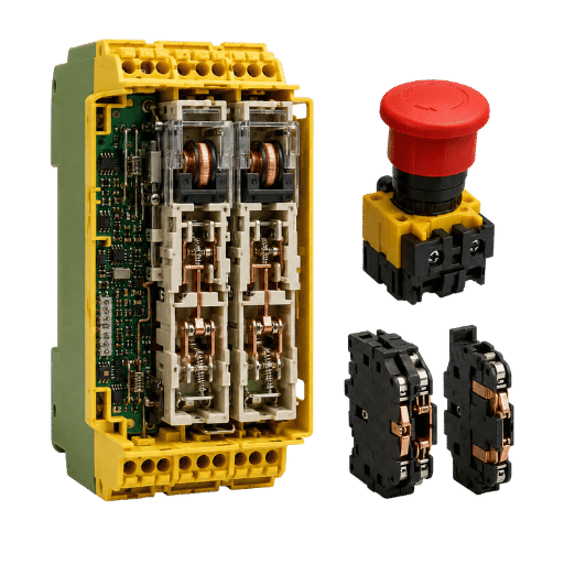
A safety relay work by reading two independent input channels from the E-stop string and enabling its outputs only when both channels agree. It continuously cross-checks those channels for discrepancy, drives force-guided output contacts, and monitors the downstream contactors through a feedback loop, dropping to a safe state the instant any channel, contact, or wire fails.
How does an emergency stop relay work?
An emergency stop relay reads two independent input channels from the E-stop string and only enables its outputs when both channels agree. If one channel open, shorts, or lags the other beyond a set discrepancy time, the relay faults and drops out. This dual-channel cross-monitoring is what lets a single wiring fault be detected instead of defeating the stop function.
Single-Fault Survival Rule: Why One Welded Contact Can’t Defeat the Stop
A compliant emergency stop circuit must keep its stop function under any single fault, a welded output, a shorted channel, or a broken wire. That’s the Single-Fault Survival Rule, and it’s the whole reason for dual channels, force-guided contacts, and the feedback loop.
On electromechanical relays, the output side uses force-guided (mechanically linked) contacts built to EN 50205, a construction documented in safety-relay patents such as US 6,661,320 B1. Because the normally-open and normally-closed contacts are tied to move as one body, a welded N.O. contact physically prevents the N.C. mirror contact from closing, so the relay’s feedback loop sees the weld and block the reset. Solid-state safety relays achieve the same fault coverage differently, using semiconductor outputs with OSSD (output signal switching device) test pulses on the safety signal and self-diagnostics rather than mechanical linkage. Either way, the design intent is identical: the relay always de-energizes to a safe state, never to a live one. A standard relay can stick closed when it fails; a safety relay is built to fail open. That fail-safe bias toward the de-energized state is what separates a safety relay from an ordinary one. In the field, this predictability is the reason a relay certified to PL e holds its diagnostic behavior even as its contacts age across a 20-year service life.
“A standard relay can fail with its contacts welded closed, which is exactly the failure you cannot tolerate in an emergency stop. The defining feature of a safety relay is the monitoring chain that detects that failure and forces the outputs open.”
Stop Categories 0, 1, and 2 (IEC 60204-1) — and Why Category 0 Isn’t Always Safest
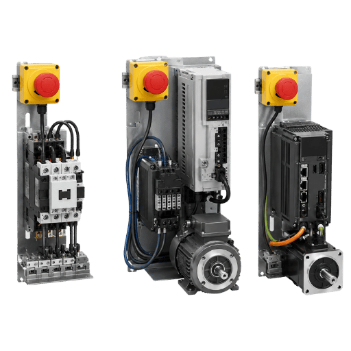
IEC 60204-1 defines three stop categories, and the wiring of your safety relay changes with the one you choose. Category 0 removes power to the actuators immediately, an uncontrolled stop. Category 1 brings the machine to a controlled stop (often a timed brake ramp) and then removes power. Kategorie 2 is a controlled stop that keeps power available at standstill. For emergency stops, the standard allows only Category 0 or Category 1ISO 13850 excludes Category 2 because an E-stop must ultimately remove the energy that can cause harm.
Here’s the part most guides skip: Category 0 isn’t automatically the safest choice. Immediate de-energization is correct for low-inertia machines that coast to a harmless stop, but on a high-inertia spindle, a robot, or a vertical axis, cutting power instantly removes the very braking that holds the hazard. The German DGUV IFA report notes that dropping out the mains contactor produce an uncontrolled Category 0 stop; on a vertical load that means the axis can drop unless a brake intervenes. CNC operators report the same thing from the field, a machine that “plunged through the part” after an E-stop because Category 0 cut power while the tool was still moving. At the drive level, Category 0 maps to Safe Torque Off (STO) and Category 1 to Safe Stop 1 (SS1) under EN 61800-5-2. The right answer come from your risk assessment, not a reflex.
Picture a press brake driven by a heavy flywheel. An integrator wires a Category 0 E-stop, reasoning that cutting power instantly must be the safest option. In practice, when the operator slaps the button the flywheel keep coasting for several seconds with no braking torque, the same behavior CNC operators describe when a Category 0 stop lets a spindle keep plunging after the button is pressed. On that machine a Category 1 stop, which commands a controlled brake ramp before it removes power, clears the hazard faster than the “instant” Category 0 it replaced. Field technicians repeat one lesson: match the category to the machine’s stored energy, not to intuition.
9-Scenario Stop-Category Routing Table
Use this routing table to match nine common machine types to the right emergency stop category and relay architecture, then confirm against your own risk assessment.
| Machine / load type | Recommended stop category | Relay / output architecture | Why |
|---|---|---|---|
| Low-inertia conveyor, small fan | Category 0 | Instantaneous safety outputs to contactor | Coasts to a harmless stop; immediate power removal is simplest and safe |
| High-inertia spindle / large flywheel | Category 1 | Time-delayed safety outputs + braking drive | Controlled brake first prevents long, dangerous coast-down |
| Vertical axis / hoist / press ram | Category 1 | Delayed output + holding-brake control | Category 0 removes the brake and the load can drop |
| Industrial robot cell | Category 1 (SS1) | Dual-channel relay → drive SS1, then STO | Controlled deceleration avoids erratic arm motion before stop |
| Servo / VFD-driven axis | Category 0 (STO) or 1 (SS1) | Relay → drive STO/SS1 safety input | Drive provides the safety stop function; relay triggers it |
| Hydraulic / pneumatic press | Category 0 or 1 | Outputs to dump valve + contactor | Must relieve stored energy, not just cut the motor |
| Heating / process equipment | Category 1 | Sequenced shutdown then power removal | Abrupt cut can create a secondary hazard |
| Multi-station line / safety gates | Mixed (zoned) | Multi-function relay or safety controller | Different zones need different stop behavior |
| Continuous web / roll-to-roll | Category 1 | Timed output + dynamic braking | Controlled stop avoids material whip and tear |
Stop categories per IEC 60204-1; STO/SS1 mapping per EN 61800-5-2. Confirm the category for your machine through an ISO 12100 risk assessment.
Designing the E-Stop Circuit: Dual-Channel Wiring, Monitored Reset, and EDM Feedback
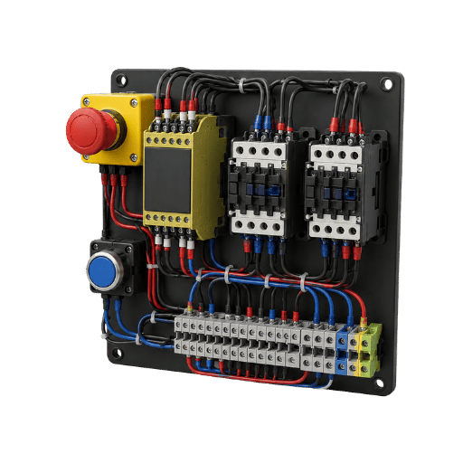
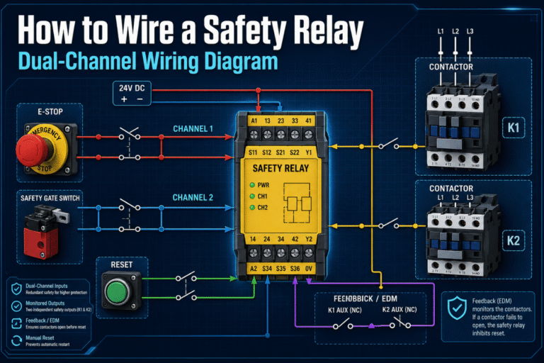
A compliant dual-channel E-stop circuit, call it the Monitored E-Stop Loophas four jobs: feed two independent channels, confirm a deliberate reset, watch the output devices, and switch the load redundantly. Install the relay on a DIN rail in the control cabinet (slim units start around 22.5 mm wide) and power it from 24 V DC on A1–A2. On a typical Pilz PNOZ-style relay the two normally-closed E-stop channels land on S11–S12 and S21–S22; the monitored manual reset wires to S33–S34; the External Device Monitoring (EDM) loop reads the contactor mirror contacts back through Y1–Y2; and the safety outputs 13–14 and 23–24 drive two contactors in series so either one can isolate the motor. Press the E-stop and both channels open, the outputs drop, and both contactors release. In practice, integrators wire this loop once for a given application and reuse it as a template across a production line, adjusting only the contactor sizing for each motor.
Technische Anmerkung
Terminal designations vary by manufacturer and model, always wire to the device manual, not a generic diagram. Two details are non-negotiable: use a monitored reset (edge-triggered on S33–S34, not a maintained jumper) so a stuck reset button can’t auto-restart the machine, and always wire the EDM loop (Y1–Y2). EDM is what actually catches a welded contactor: if a mirror contact fail to reopen, the relay refuses to re-enable. Skipping EDM is the most common way an “expensive safety relay” silently degrades to an ordinary power relay.
Architecture sets the ceiling, not the achieved result. Two cross-monitored channels, force-guided outputs, and EDM feedback give the structure of a Category 3 or 4 subsystem under ISO 13849-1:2023capable of PL d or PL e. But a relay’s capability is not your machine’s achieved Performance Level: that depends on the whole chain (Category, mean time to dangerous failure, diagnostic coverage, and common-cause factors, evaluated over the 20-year mission time ISO 13849-1 assumes), and the weakest link drags the system down. A PL e relay wired behind a single-channel button does not give you PL e.
Standards You Must Meet: ISO 13850, IEC 60204-1, NFPA 79, and ISO 13849 PL
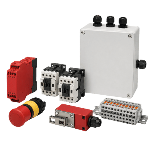
Four documents govern an emergency stop circuit, and each covers a different layer. ISO 13850:2015 defines the emergency stop functionit must latch, require a deliberate manual reset, take priority over all other functions, and act only as a complementary protective measure that never substitutes for guarding. IEC 60204-1 covers the electrical equipment of machines and is where the stop categories 0/1/2 are defined; its European harmonized version, EN 60204-1:2018, was amended by A1:2025. NFPA 79 is the North American counterpart for industrial machinery wiring. And ISO 13849-1:2023 is where you calculate the required Performance Level (PLr) from the risk and verify the design reaches it.
In the United States, OSHA does not publish a relay spec, but its machine-guarding rules, for example 29 CFR 1910.212make the employer responsible for a control system that protects the operator, which in practice means a monitored stop circuit built around a relay certified to ISO 13849-1. Verify each standard’s scope before you cite it: ISO 13850 is the function, IEC 60204-1 is the electrical/category layer, and ISO 13849-1 is the math. Treating them as interchangeable is how a design looks compliant on paper but fails an audit.
Choosing a Safety Relay: Single vs Dual Channel, PL Rating, Reset, and Multi-Function
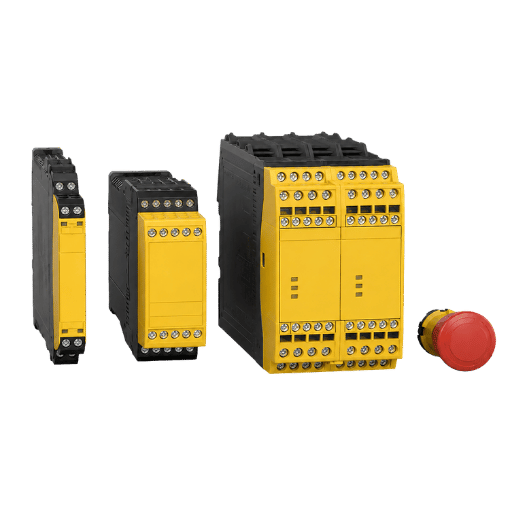
The first decision is channel count, and it follows directly from your required Performance Level. Single-channel relays are cheaper and simpler but can’t detect every fault; dual-channel cross-monitored relays are what most E-stop circuits need to reach Category 3/4 and PL d/e.
✔ Dual-channel
- Detects cross-faults, shorts, and channel discrepancy
- Reaches up to Category 4 / PL e / SIL 3
- Required for most hazardous machinery
⚠ Single-channel
- Lower cost, simpler wiring
- Can’t detect all faults; a short can defeat the stop
- Typically limited to lower PL / low-risk machines
The cost of getting this wrong show up in audits. A small machine builder, wanting to trim the bill of materials, drops a single-channel relay onto a robot cell rated PL d by its risk assessment. It runs fine for a year, until a safety auditor traces the E-stop loop and finds a single shorted wire could hold the circuit “closed” and defeat the stop. The machine is red-tagged until a dual-channel relay is retrofitted, at far more cost than the original part saved. Channel count is set by the required Performance Level, not by the purchase-order line item.
After channels, match the rest of the spec to the job: the reset type (automatic for simple zones, monitored manual where re-start visibility matters), the number and type of safety functions, and the output rating versus the contactors you must drive. One safety relay often monitors more than an E-stop, the same input class handles Sicherheitslichtvorhänge and other presence-sensing safety sensors, safety gates, two-hand controls, and safety mats, so size the input count for everything the cell needs. Our Sicherheitsrelaismodule and the safety relay module selector walk through this for the SR-Series, which is rated to SIL 3 / PL e and built under triple ISO 9001/14001/45001 certification with CE and TÜV approval; pair it with the PL/SIL category mapper to confirm the target rating. When a machine has many safety devices or needs per-device diagnostics, that is the point to graduate from a hardwired relay to a safety PLC, see the SR-series safety relays guide for where that line sits.
Why E-Stop Circuits Fail: Welded Contacts, Channel Discrepancy, and Nuisance Trips
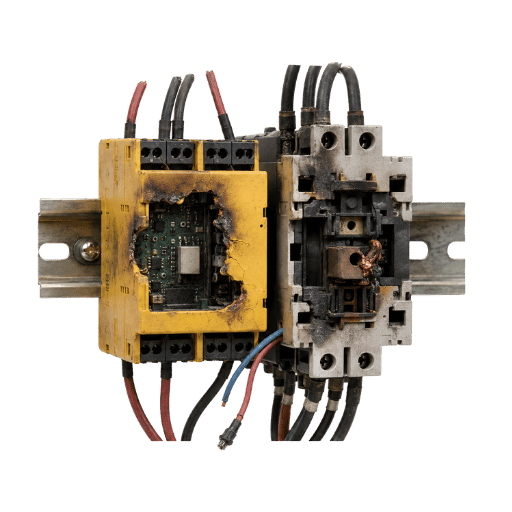
Most E-stop faults aren’t exotic, they’re predictable wiring and selection mistakes. Field reports from automation practitioners point to the same handful of root causes again and again. Each entry in the taxonomy below maps a failure mode to its cause, the symptom you’ll see, and the standard-aligned prevention.
One scenario recurs in those field reports from production lines: a panel builder skips the EDM loop to save a little wiring time, and the circuit test perfectly on commissioning. Months later a motor contactor welds closed. Because nothing is monitoring that contactor, the operator hits the E-stop, the relay drops its outputs as designed, yet the motor keep turning. Ironically, a circuit bought specifically to prevent a silent failure now has one, and no indicator light shows it. That single skipped feedback loop is why EDM is treated as mandatory, not optional, on any output that drives a contactor.
| Failure mode | Wurzelursache | Symptom | Prevention |
|---|---|---|---|
| Welded output contact | Load over-rated / no contactor | Machine won’t stop on E-stop | Use contactors sized to the load; wire EDM |
| Kanaldiskrepanzfehler | Asymmetric contact wear / wiring | Relay faults, won’t reset | Maintain both channels; replace worn buttons |
| Missing / wrong EDM | Feedback loop not wired | Welded contactor goes undetected | Always close the Y1–Y2 loop on mirror contacts |
| Single-channel where dual required | Under-specified for the PLr | A short defeats the stop | Match channel count to the risk assessment |
| Maintained (not monitored) reset | Reset jumpered or held | Machine auto-restarts after fault | Use edge-triggered monitored reset (S33–S34) |
| Wire short across a channel | Chafed cable / shared conduit | One channel always “closed” | Route channels separately; rely on OSSD test pulses |
| Nuisance trip on reset | Slow contact / interlock lag | Random faults, downtime | Check discrepancy time; clean/replace switches |
| Ground fault on input | Insulation breakdown | Relay trips or won’t enable | Proper earthing and fusing per IEC 60204-1 |
| Wrong stop category | Cat 0 on a coasting/vertical load | Hazardous coast-down or load drop | Re-derive category from risk assessment |
️ Wichtig
The single most common — and most dangerous — mistake is omitting the EDM feedback loop. Without it, a welded motor contactor is invisible to the relay, and the machine keeps running power to the load even after a valid E-stop. This is exactly the single-failure scenario that the control-reliability expectation behind OSHA 29 CFR 1910.212 is meant to prevent. Wire EDM on every safety output that drives a contactor.
Where E-Stop Safety Design Is Heading
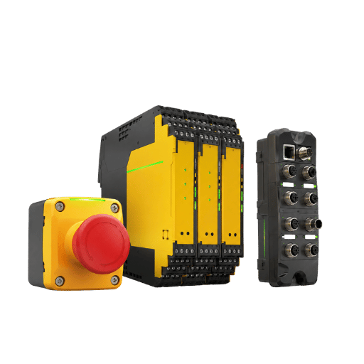
Two shifts are worth planning for. First, the standards keep moving: the European EN 60204-1:2018 picked up Amendment A1:2025, and ISO 13849-1 was reissued in 2023, if your documentation still cites the older editions of either standard, a 2026 functional-safety audit will almost certainly flag the gap and ask for a re-validation.
Second, the design center of gravity is moving from fixed “category” thinking toward full functional-safety design built around Performance Level and SIL, and from hardwired relays toward programmable safety controllers and safe-fieldbus on larger machines. Industry analysts estimate the machine-safety market growing from roughly USD 5 billion toward USD 7 billion by the end of the decade, with emergency-stop and shutdown functions a leading segment.
A third pressure is converging on E-stop design: as machines join networks, the safety circuit has to stay isolated from the security attack surface, which is pushing wider adoption of dedicated safe-fieldbus links (such as the FSoE and PROFIsafe protocols layered on standard networks) instead of one long hardwired loop on large lines.
For most single-cell production machines, a well-designed hardwired emergency stop safety relay remains, in practice, the simplest, most transparent, and most cost-effective way to reach PL e with a certified, off-the-shelf part. If you are planning a 2026 project, three practical actions follow from the above: re-verify your required Performance Level at the next risk-assessment review; confirm your documentation cites the current standard editions (ISO 13850:2015, ISO 13849-1:2023, and the current IEC 60204-1 with EN 60204-1:2018/A1:2025); and audit every existing E-stop circuit for the one failure that hides best, a missing EDM loop on a contactor output.
Häufig gestellte Fragen
Q: How does an emergency stop relay work?
Antwort anzeigen
An emergency stop relay reads two independent input channels from the E-stop string and enables its outputs only when both channels agree. If a channel opens, shorts, or lags beyond the discrepancy time, the relay drops its force-guided outputs to a safe state and blocks reset until the fault clears. A feedback (EDM) loop also watches the downstream contactors so a welded contact is detected rather than hidden.
Q: Why use a safety relay instead of wiring the E-stop directly to the contactor?
Antwort anzeigen
A button wired straight to a contactor has no way to detect a welded contactor, a shorted channel, or a broken wire — the circuit can fail silently and the machine becomes unstoppable with no warning. A safety relay adds continuous self-monitoring and a deliberate-reset requirement, converting a circuit that can fail dangerously into one that fails to a safe state. It is also what lets the stop function reach a defined, auditable Performance Level under ISO 13849-1.
Q: What stop category should an emergency stop use?
Antwort anzeigen
For an emergency stop, IEC 60204-1 allows only Category 0 (immediate power removal) or Category 1 (controlled stop then power removal); Category 2 is excluded. Use Category 0 for low-inertia machines that stop safely on de-energization, and Category 1 for high-inertia, vertical-axis, or coasting machines where cutting power instantly would be hazardous. The choice should come from an ISO 12100 risk assessment, not a default.
Antwort anzeigen
Not always — it depends on the required Performance Level from your risk assessment. Low-risk machines may permit a single channel, but most hazardous machinery needs dual-channel cross-monitoring to reach Category 3 or 4 and PL d/e. When the assessment lands in a borderline band, default to dual-channel; the part-cost difference is small next to a red-tagged machine.
Q: What causes a safety relay to nuisance trip?
Antwort anzeigen
Most nuisance trips are channel-discrepancy faults: one E-stop or interlock contact opens or closes more slowly than the other, so the relay sees the two channels disagree beyond its discrepancy time. Worn buttons, slow magnetic interlocks, and miswired feedback loops are common culprits.
Antwort anzeigen
Yes. Wire multiple E-stop buttons in series on each channel, so any single press breaks the loop. Add an auxiliary contact per button to flag which one was pressed.
Need a safety relay sized to your stop category and PL?
QJKH builds SR-Series safety relay modules rated to SIL 3 / PL e for E-stop, safety-gate, and light-curtain monitoring, certified to ISO 13849-1 and IEC 60204-1. As a factory-direct manufacturer, we can match the relay to your stop category, channel count, and contactor sizing, and ship single- or dual-channel modules with the EDM and reset options your risk assessment calls for.
About This Guide
This article was prepared by the engineering team at CCH Shanghai Sensing Intelligence Technology (QJKH), a manufacturer of safety light curtains, laser scanners, LiDAR, and SR-Series safety relay modules since 2003. The stop-category routing and failure-mode guidance here reflects the IEC 60204-1 and ISO 13850 framework we design our SIL 3 / PL e relay modules to meet. Always confirm the required stop category and Performance Level for your machine through your own ISO 12100 risk assessment.
Referenzen und Quellen
- ISO 13850:2015, Safety of machinery: Emergency stop functionInternationale Organisation für Normung
- ISO 13849-1:2023, Safety-related parts of control systemsInternationale Organisation für Normung
- NFPA 79, Electrical Standard for Industrial MachineryNational Fire Protection Association
- 29 CFR 1910.212, Allgemeine Anforderungen für alle MaschinenUS-amerikanische Arbeitsschutzbehörde
- IFA Report 4/2018, Functional safety of machine controlsDGUV (German Social Accident Insurance)
- US Patent 6,661,320 B1, Safety relayUnited States Patent and Trademark Office